


Software apps and online services
- Arduino IDE
Hand tools and fabrication machines
- Soldering iron (generic)
- Solder Wire, Lead Free
Story
The main problem of visually impaired persons (VIPs) can't properly see things, so they need some bi-standards or assistance to do their tasks. They can't see. but they can speak, here I build a voice-controlled wheelchair. so a person with a visual problem can use their voice to control and use the wheelchair. This wheelchair has floor floor-detection feature also. So we don't worry about the stairs.
Components needed
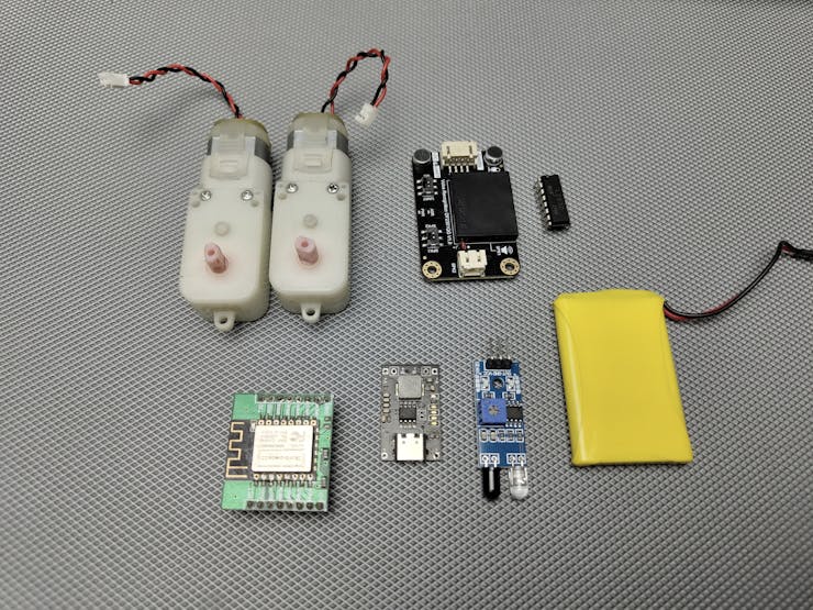
1. ESP12E Microcontroller
2. DFRobot voice recognition module
3. L293D motor Driver
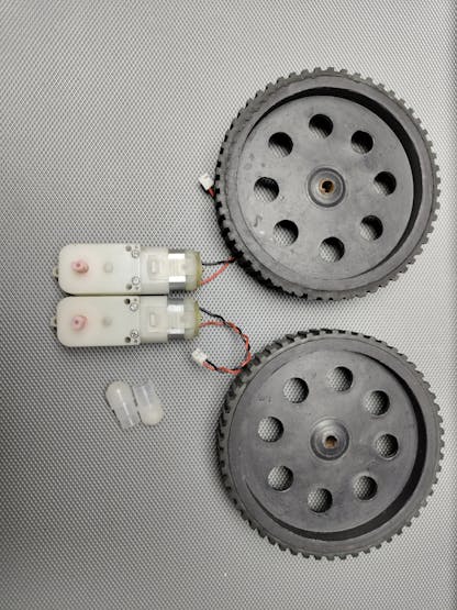
4. 2*BO Motors
5. 2*BO motor wheels
6. Custom PCB
7. 3.7v li-ion battery
8.1or 2 castor wheels
9. 3.7v to 5v booster module
10. 3D printed chair model base
1. ESP12E Microcontroller-This is a Wi-Fi-enabled microcontroller based on the ESP8266 chip. It will act as the brain of your project, controlling the motors, receiving commands from the voice recognition module, and potentially connecting to other devices over Wi-Fi.
2. DFRobot offline Voice Recognition Module-This module will allow your project to recognize and respond to voice commands. It will be connected to the ESP12E, which will interpret the recognized commands and control the motors or other functions accordingly.
3.L293D Motor Driver- The L293D is a dual H-bridge motor driver that allows you to control the speed and direction of two DC motors independently. The ESP12E sends control signals to the L293D to drive the motors.
4. 2 * BO Motors- These are the DC motors that will drive the wheelchair.
5. 2 * BO Motor Wheels- These wheels will be attached to the BO motors, allowing the wheelchair to move around.
6. Custom PCB- A custom PCB will be designed to neatly integrate all the components, making the assembly easier and more reliable.
7. 3.7V Li-ion Battery- This battery will power your entire project, providing power to the ESP12E, motors, and other components. I chose lithium-ion batteries because Li-ion batteries are compact and have a good energy density.
8. 1 or 2 Castor Wheels - Castor wheels provide balance and support for your project, allowing it to move smoothly in different directions without tipping over.
9. 3.7V to 5V Booster Module- Since some components (like the motor driver) require 5V to operate, this booster module will step up the 3.7V from the Li-ion battery to a stable 5V output.
10. 3D Printed Chair Model Base- This is the structure or frame that holds all the components together. It will be designed to house the motors, wheels, and electronics, forming the physical base of this project.
Tools needed
1. Glue gun
2. soldering iron
3. Soldering flux
4. soldering lead
5. cutter
6. Screwdriver
Apps/software needed
1. Arduino IDE
2.EasyEDA
3. Tinkercad
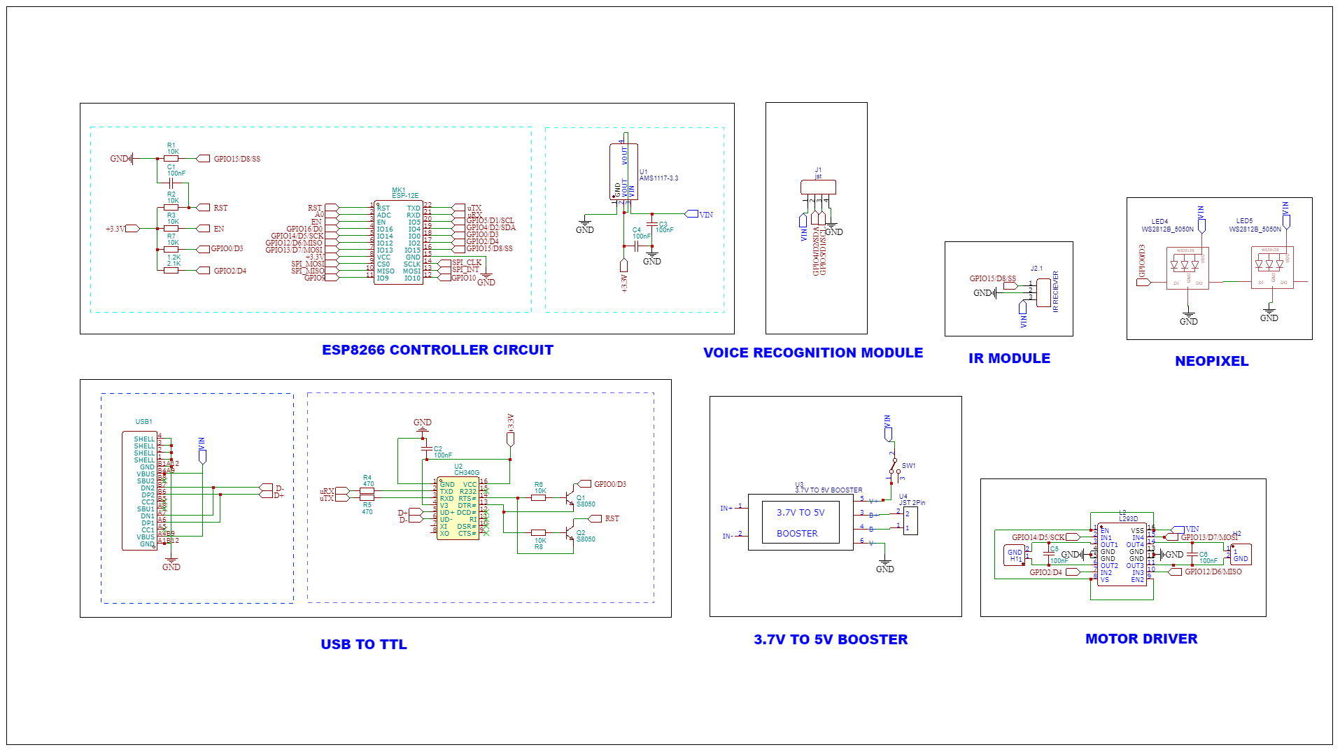
Circuit Diagram
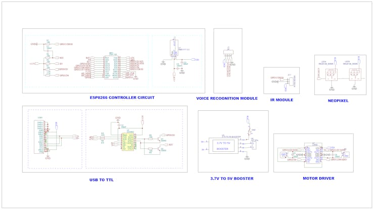
The main component of this circuit is the ESP8266 Module, This is the core microcontroller that controls the entire system. The various GPIO (General Purpose Input/Output) pins are connected to different components and modules. RST (Reset) and EN (Enable) are control pins for resetting and enabling the ESP8266. AMS1117-3.3 Voltage Regulator.Converts 5 volts down to 3.3V, which powers the ESP8266.Capacitors (C1, C2, C3, C4) stabilize the power supply to the ESP8266 by filtering out noise. The offline voice recognition module is connected to the i2c pins of esp8266. IR Receiver module detects the floor and The signal pin is connected to A0 pin ESP8266. CH340G USB to Serial Converter: This circuit converts USB signals to TTL (Transistor-Transistor Logic) level signals. It’s used for programming or communicating with the ESP8266 from a computer.3.7V to 5V Booster This boosts a 3.7V input ( from Li-ion battery) to 5V. L293D Motor Driver drives the motors. It can control the direction of the motors by switching the polarity. GPIO D6, D7, D8 and D9 these pins from the ESP8266 are used to control the motor driver.
PCB designing
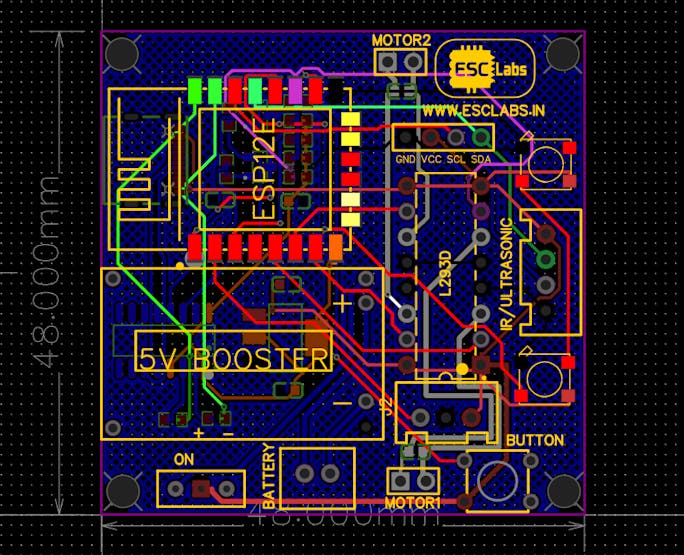
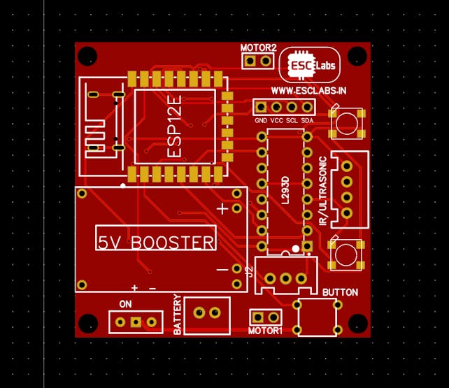
After testing and verifying the circuit using nodemcu on a breadboard, I decided to finalise the PCB design. So I converted the circuit diagram into a PCB. I arranged all the components closely and I finished the PCB design. The PCB looks something like this after designing. after varifing the PCB design once again I downloaded the Gerber files for PCB fabrication.
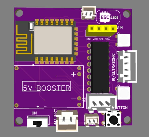
PCB fabrication
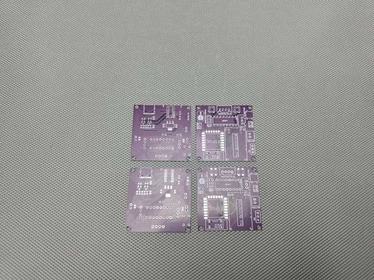
To fabricate the designed PCBs I went to jlcpcb.com. You will get 10 PCBs for just 5$. After logging in to your account, Click on Order now and upload the gerber file, after that, we can select colour, quantity, thickness etc. Here I choose purple colour for my PCBs. You can choose any colour. Then we can select the shipping method and we can place the order
3D designing
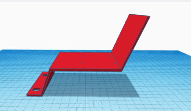
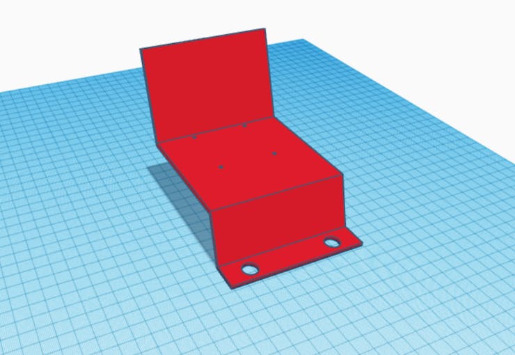
Now I need to build the model wheelchair. so with the help of tinkercad, I designed a simple 3D model.
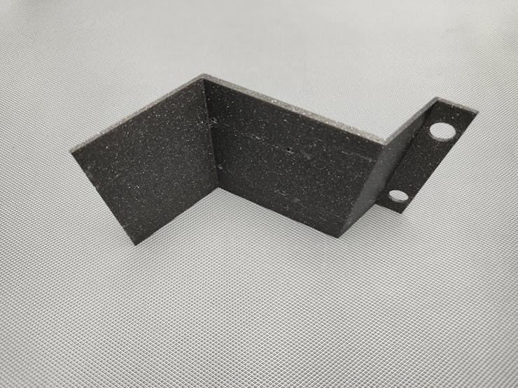
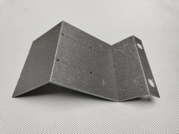
I used my flashforge adventurer 5m Pro for printing the models. I used PLA filament for printing.
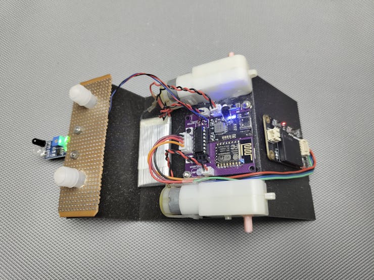
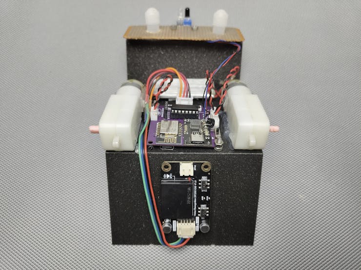
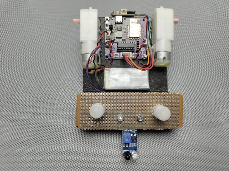
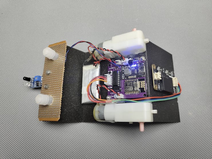
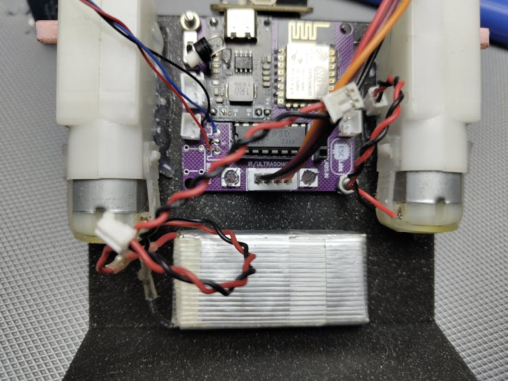
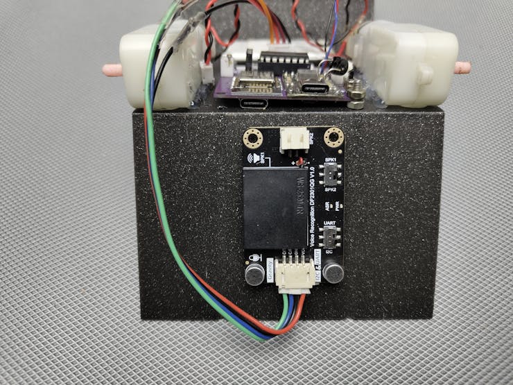
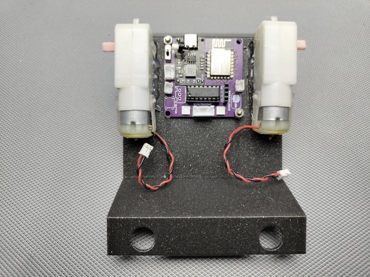
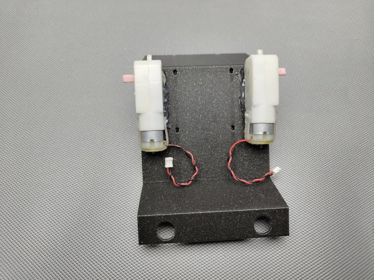
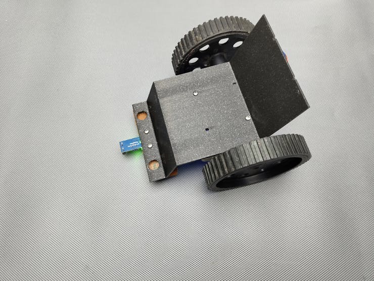
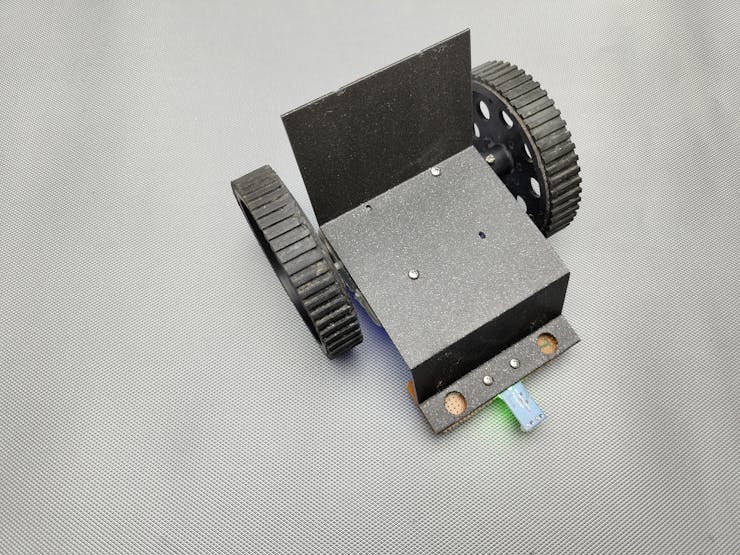
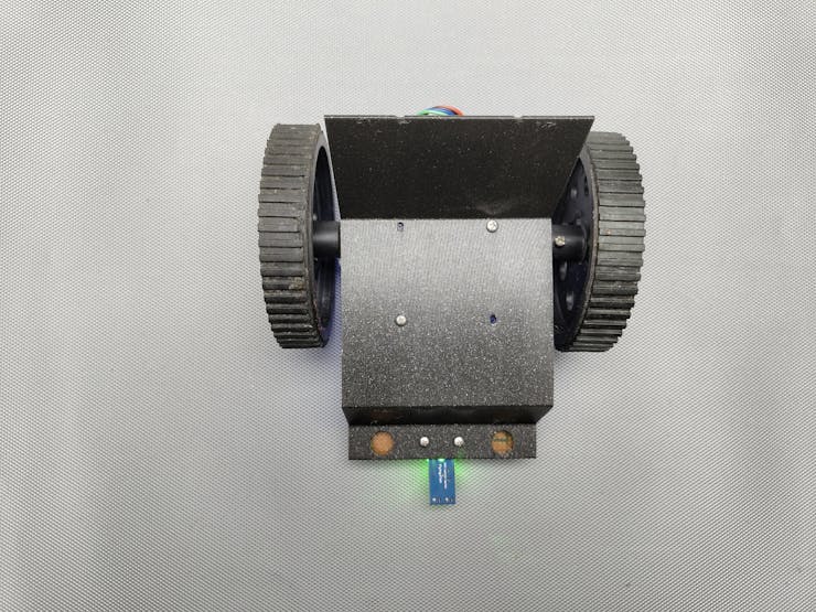
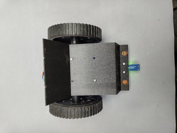
Making the model wheelchair
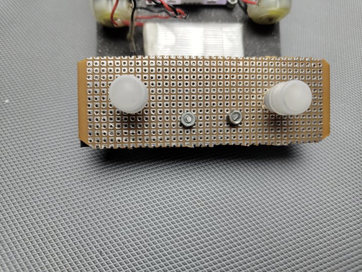
first, I placed the motors in the wheelchair model then I placed the main PCB. I attached the voice recognition module to the backside of the wheelchair. I attached the infrared module to the front side of the chair, so it can easily detect the floor.
Preparing the offline voice recognition module
we need to teach commands to the voice recognition module for that, turn on the circuit and
Use a wake-up word (default or learned) to wake up the voice assistant, and then say "Learning command word" to initiate the process of learning command phrases, following the provided prompts. Before each session of learning command phrases, it is necessary to delete the previously learned command phrases. Please refer to instructions on how to delete wake-up words and command phrases.
- Indication: Learning now, be quiet, please learn the command word according to the prompt! Please say the first command to be learned!
- Command phrase to be learned (using "go forward" as an example): "go forward"
- Indication: Learning successful, please say it again!
- Command phrase to be learned: "go forward"
- Indication: Learning successful, please say it again!
- Command phrase to be learned: "go forward"
- Indication: OK, learned the first command successfully! Please say the second command to be learned!
... (Continue learning)
thesame way you have to add turn left, turn right and stop. please watch this tutorial video about the voice recognition module.
Arduino programming
you can find the complete Arduino code at the end of this article
#include "DFRobot_DF2301Q.h"
DFRobot_DF2301Q_I2C asr;
#include <FastLED.h>
#define NUM_LEDS 2
#define DATA_PIN 0
CRGB leds[NUM_LEDS];
- DFRobot_DF2301Q.h: This library is used to interact with the DFRobot DF2301Q, a voice recognition module
- FastLED.h: This library is used to control Neopixel (WS2812) LEDs.
- NUM_LEDS: The number of LEDs connected.
- DATA_PIN: The pin connected to the Neopixel data line.leds[]: An array to store the colour data for each LED.
#define IN_1 2
#define IN_2 14
#define IN_3 13
#define IN_4 12
- IN_1, IN_2, IN_3, IN_4: These are the GPIO pins connected to the motor driver inputs that control the robot's motors.
void setup() {
  Serial.begin(115200);
  while (!(asr.begin())) {
    Serial.println("Communication with device failed, please check connection");
    delay(3000);
  }
   FastLED.addLeds<NEOPIXEL, DATA_PIN>(leds, NUM_LEDS);
   pinMode(IN_1, OUTPUT);
   pinMode(IN_2, OUTPUT);
   pinMode(IN_3, OUTPUT);
   pinMode(IN_4, OUTPUT);

  Serial.println("Begin ok!");
  asr.setVolume(10);
  asr.setMuteMode(0);
  asr.setWakeTime(100);
  uint8_t wakeTime = 0;
  wakeTime = asr.getWakeTime();
  Serial.print("wakeTime = ");
  Serial.println(wakeTime);
}
- Serial Communication: Starts the serial communication at a baud rate of 115200 for debugging.
- Voice Module Initialization: The code attempts to initialize the voice recognition module. If it fails, a message is printed, and it waits for 3 seconds before retrying.
- LED Initialization: The Neopixel LEDs are initialized using the FastLED.addLeds function.
- Motor Control Pins: The motor driver pins are set as outputs.
Voice Module Settings:
- asr.setVolume(10): Sets the volume level.- asr.setMuteMode(0): Unmutes the module.- asr.setWakeTime(100): Sets the wake-up time for the voice module.- The wake time is read back and printed for confirmation.- Voice Module Settings:
asr.setVolume(10): Sets the volume level.
asr.setMuteMode(0): Unmutes the module.
asr.setWakeTime(100): Sets the wake-up time for the voice module.
The wake time is read back and printed for confirmation.
void loop() {
 int flooor= analogRead(A0);
  uint8_t CMDID = asr.getCMDID();
  if ((CMDID == 22) && (flooor<500))
  {      Serial.println("22") ;
       goAhead();
       }
       if ((CMDID == 6) && (flooor<500))
  {      Serial.println("6") ;
       goRight();
       }
        if ((CMDID == 7) && (flooor<500))
  {      Serial.println("7") ;
       goLeft();
       }
       if ((CMDID == 8)||(flooor>1000))
  {      Serial.println("8") ;
       goBack();
       }
  delay(300);
}
Voice Command Handling: The voice recognition module listens for commands, identified by CMDID.
- CMDID == 22: Move forward if the floor condition is met.
- CMDID == 6: Turn right if the floor condition is met.
- CMDID == 7: Turn left if the floor condition is met.
- CMDID == 8: Move backward, or if the floor condition triggers the robot to stop or reverse.
- Voice Command Handling: The voice recognition module listens for commands, identified by CMDID.
CMDID == 22: Move forward if the floor condition is met.
CMDID == 6: Turn right if the floor condition is met.
CMDID == 7: Turn left if the floor condition is met.
CMDID == 8: Move backwards, or if the floor condition triggers the robot to stop or reverse.
4. Movement Functions
- goAhead(): Moves the robot forward. The motor driver inputs are set to move the motors in the forward direction, and the Neopixel LEDs are set to magenta.
void goAhead(){
      digitalWrite(IN_1, LOW);
      digitalWrite(IN_2, HIGH);
      digitalWrite(IN_3, LOW);
      digitalWrite(IN_4, HIGH);
      leds[0] = CRGB::Magenta;
      leds[1] = CRGB::Magenta;
      FastLED.show();
      delay(50);
}
void goRight(){
      digitalWrite(IN_1, HIGH);
      digitalWrite(IN_2, LOW);
      digitalWrite(IN_3, LOW);
      digitalWrite(IN_4, HIGH);
      leds[0] = CRGB::Green;
      leds[1] = CRGB::Green;
      FastLED.show();
      delay(50);
}
void goLeft(){
      digitalWrite(IN_1, LOW);
      digitalWrite(IN_2, HIGH);
      digitalWrite(IN_3, HIGH);
      digitalWrite(IN_4, LOW);
      leds[0] = CRGB::Blue;
      leds[1] = CRGB::Blue;
      FastLED.show();
      delay(50);
}
void stopRobot(){
      digitalWrite(IN_1, LOW);
      digitalWrite(IN_2, LOW);
      digitalWrite(IN_3, LOW);
      digitalWrite(IN_4, LOW);
      leds[0] = CRGB::Red;
      leds[1] = CRGB::Red;
      FastLED.show();
      delay(50);
}
Custom parts and enclosures
- 3d printing files (Sketchfab still processing.)
Schematics
circuit digram
#include "DFRobot_DF2301Q.h"
DFRobot_DF2301Q_I2C asr;
#include <FastLED.h>
#define NUM_LEDS 2
#define DATA_PIN 0
CRGB leds[NUM_LEDS];
#define IN_1  2
#define IN_2  14
#define IN_3  13
#define IN_4  12

void setup() {
  Serial.begin(115200);
  while (!(asr.begin())) {
    Serial.println("Communication with device failed, please check connection");
    delay(3000);
   FastLED.addLeds<NEOPIXEL, DATA_PIN>(leds, NUM_LEDS);
 pinMode(IN_1, OUTPUT);
 pinMode(IN_2, OUTPUT);
 pinMode(IN_3, OUTPUT);
 pinMode(IN_4, OUTPUT);
  }
  Serial.println("Begin ok!");
  asr.setVolume(10);
  asr.setMuteMode(0);
  asr.setWakeTime(100);
  uint8_t wakeTime = 0;
  wakeTime = asr.getWakeTime();
  Serial.print("wakeTime = ");
  Serial.println(wakeTime);
}
void loop() {
 int flooor= analogRead(A0);
  uint8_t CMDID = asr.getCMDID();
  if ((CMDID == 22) && (flooor<500))
  {      Serial.println("22") ;
       goAhead();
       }
       if ((CMDID == 6) && (flooor<500))
  {      Serial.println("6") ;
       goRight();
       }
        if ((CMDID == 7) && (flooor<500))
  {      Serial.println("7") ;
       goLeft();
       }
       if ((CMDID == 8)||(flooor>1000))
  {      Serial.println("8") ;
       goBack();
       }
  delay(300);

}


void goAhead(){

      digitalWrite(IN_1, LOW);
      digitalWrite(IN_2, HIGH);


      digitalWrite(IN_3, LOW);
      digitalWrite(IN_4, HIGH);
      leds[0] = CRGB::Magenta;
  leds[1] = CRGB::Magenta;
  FastLED.show();
  delay(50);

  }

void goBack(){

      digitalWrite(IN_1, LOW);
      digitalWrite(IN_2, LOW);


      digitalWrite(IN_3, LOW);
      digitalWrite(IN_4, LOW);
       leds[0] = CRGB::Cyan;
  leds[1] = CRGB::Cyan;
  FastLED.show();
  delay(50);
  }

void goRight(){

      digitalWrite(IN_1, HIGH);
      digitalWrite(IN_2, LOW);


      digitalWrite(IN_3, LOW);
      digitalWrite(IN_4, HIGH);
         leds[0] = CRGB::Green;
  leds[1] = CRGB::Green;
  FastLED.show();
  delay(50);
  }

void goLeft(){

      digitalWrite(IN_1, LOW);
      digitalWrite(IN_2, HIGH);


      digitalWrite(IN_3, HIGH);
      digitalWrite(IN_4, LOW);
          leds[0] = CRGB::Blue;
  leds[1] = CRGB::Blue;
  FastLED.show();
  delay(50);

  }


void stopRobot(){

      digitalWrite(IN_1, LOW);
      digitalWrite(IN_2, LOW);


      digitalWrite(IN_3, LOW);
      digitalWrite(IN_4, LOW);
          leds[0] = CRGB::Red;
  leds[1] = CRGB::Red;
  FastLED.show();
  delay(50);

 }
This article was first published on Hackster on August 29, 2024
cr: https://www.hackster.io/e_s_c/voice-assisted-wheel-chair-for-visually-impaired-persons-61e5a8
Author: edison science corner


