
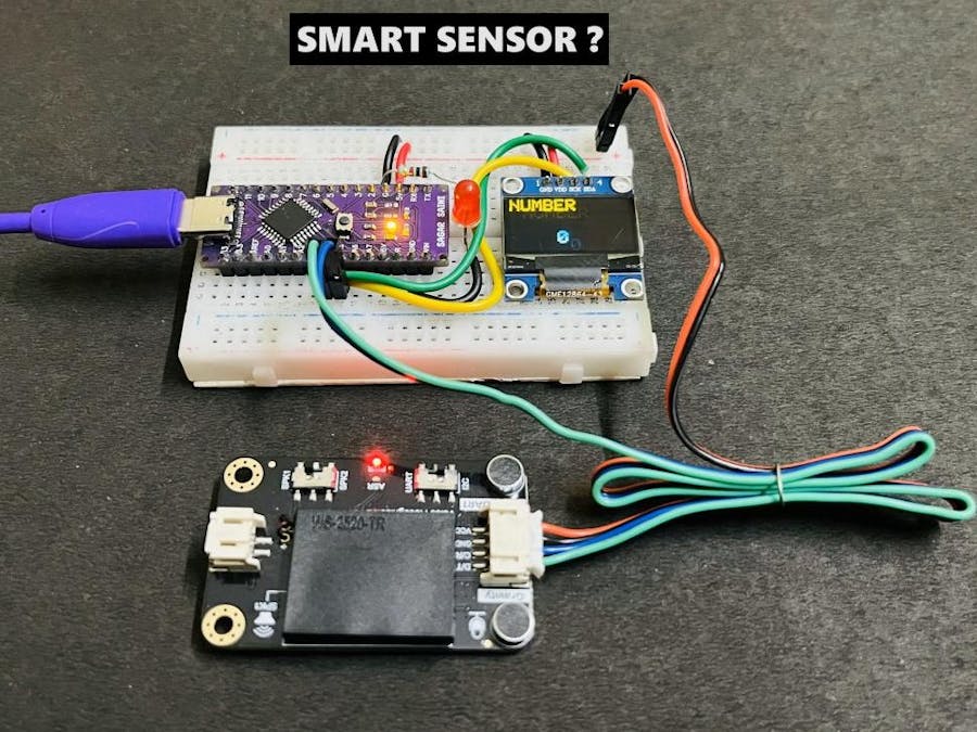
With DF2301 DF robot offline voice recognition module now controlling the GPIOs of a microcontroller over voice commands is possible.
Story
In the previous tutorial we discussed the word organization, setup and configuration of DF2301 Offline voice recognition module. Today we will make a home automation project using the same module with Solid state relay interface for small loads. But first we will try some circuit controlling lights using the voice commands and then build the hardware accordingly. This tutorial has two parts. In the first I will do some tests on the breadboard and in the second I will show the PCB that I have built for Home automation. The reason behind using the solid state relay is to reduce the overall form factor. I want to fit the module and microcontroller in a switch board to control the appliances.
DF2301 Offline voice recognition module has inbuilt commands for lights, fans and we can also record some custom controls to set up other cob lights and small loads. The solid state relay is controlled with TRIAC, which is just a bidirectional AC switch and separate controllers are available there to make them more usable. Transform your concepts into flawless PCBs with JLCPCB's advanced manufacturing expertise. Try now from here just in $2 for 5 pcs of 2layer board.
TRIAC control:
TRIAC is basically a thyristor, which is used to control the AC supply. Either it can turn on/off the load or control the load by modulating the firing angle or we can say dim the overall output. But here in the circuit the TRIAC is used as a simple switch as relay to on/off the devices. TRIAC do not need high power dissipation because it is controlled by firing pulse on gate. And for controlling the firing pulse TRAIC drive circuitry is required, which may need timing accuracy but here we are using an IC(MOC3021) as driver.
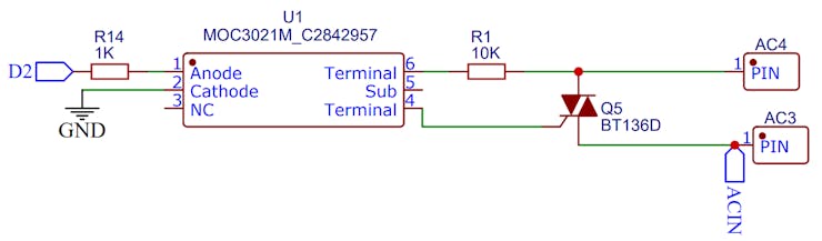
Solid State Relay (SSR) is an electronic switching device that uses semiconductor components to perform the same function as a traditional electromechanical relay. However, SSRs have certain advantages over traditional relays, including faster switching speeds, longer operational life, and the absence of moving parts. Here the switching character totally depends on the circuitry we are using, TRIAC may have different ratings which should be taken care of while designing the circuit for higher loads.
Setup of Voice recognition module Commands:
I Have posted a whole article explaining the commands, wake words and custom words. Check that tutorial from here, in this voice recognition module custom commands can be recorded in any language and then those commands can be used to control the GPIOs of the microcontroller.
The training of the ML module on new custom commands is very easy and all the steps can be found in the previous tutorial. Keep all your custom commands written on a page and train the module in one go. Because there is no option to continue from the next command once exit from the learning mode.
Circuit Diagram for breadboard testing:
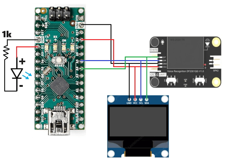
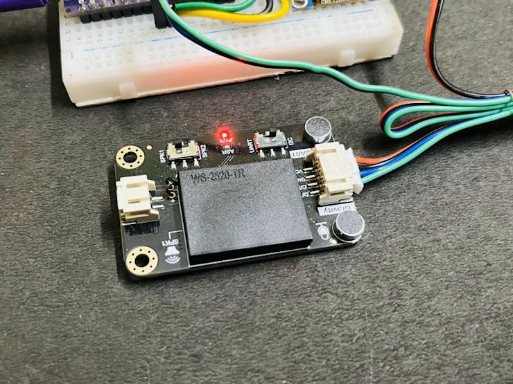
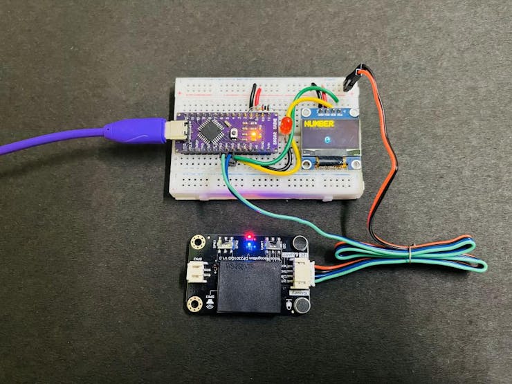
For the testing purpose we are using a breadboard setup, on which Display SSD1306 is connected via the same I2C port in which Module is connected. I2C supports up to 127 devices with different addresses. Whole the system is powered directly by the USB power from the Arduino. A LED is also connected with Digital pin 2 of Arduino Nano. The code can be programmed as per 2 devices here functions to ON/OFF the LED and display some number on SSD1306 display. GND terminal of all the peripherals remains common.
Arduino code for test:
This is the code to test the breadboard circuit only.
#include "DFRobot_DF2301Q.h"
#include <SPI.h>
#include <Wire.h>
#include <Adafruit_GFX.h>
#include <Adafruit_SSD1306.h>
#define SCREEN_WIDTH 128 // OLED display width, in pixels
#define SCREEN_HEIGHT 64 // OLED display height, in pixels
#define light 2 // relay is connected to the digital pin D4
//I2C communication
DFRobot_DF2301Q_I2C asr; // activates the I2C mode of the voice recognition module
#define OLED_RESET     -1 // Reset pin # (or -1 if sharing Arduino reset pin)
#define SCREEN_ADDRESS 0x3C ///< See datasheet for Address; 0x3D for 128x64, 0x3C for 128x32
Adafruit_SSD1306 display(SCREEN_WIDTH, SCREEN_HEIGHT, &Wire, OLED_RESET);
void setup() {
Serial.begin(115200);
Wire.begin();
display.begin(SSD1306_SWITCHCAPVCC, 0x3C);
display.clearDisplay();
pinMode(light, OUTPUT);    //Init light pin to output mode
digitalWrite(light, LOW);  //Set light pin to low
// Init the sensor
while (!(asr.begin())) {
Serial.println("Communication with device failed, please check connection");
delay(3000);
}
Serial.println("Begin ok!");
/**
* @brief Set voice volume
* @param voc - Volume value(1~7)
*/
asr.setVolume(7);
/**
@brief Set mute mode
@param mode - Mute mode; set value 1: mute, 0: unmute
*/
asr.setMuteMode(0);
/**
@brief Set wake-up duration
@param wakeTime - Wake-up duration (0-255)
*/
asr.setWakeTime(20);
/**
@brief Get wake-up duration
@return The currently-set wake-up period
*/
uint8_t wakeTime = 0;
wakeTime = asr.getWakeTime();
Serial.print("wakeTime = ");
Serial.println(wakeTime);
asr.playByCMDID(1);   // Wake-up command
/**
@brief Play the corresponding reply audio according to the ID
@param CMDID - command word ID
*/
//asr.playByCMDID(23);  // Command word ID
}
void loop() {
/**
@brief Get the ID corresponding to the command word
@return Return the obtained command word ID, returning 0 means no valid ID is obtained
*/
uint8_t CMDID = asr.getCMDID();
Serial.println(CMDID);
switch (CMDID) {
case 103:   //If the command is “Turn on the light”
digitalWrite(light, HIGH);  //Turn on the light
break;
case 104:  //If the command is “Turn off the light”
digitalWrite(light, LOW);  //Turn off the light
break;
case 52: // Display number zero
display.clearDisplay();
display.setTextSize(2);
display.setTextColor(WHITE);
display.setCursor(0,0);
display.print("NUMBER");
display.setCursor(50,40);
display.print("0");
display.display();
break;
case 53: // Display number zero
display.clearDisplay();
display.setTextSize(2);
display.setTextColor(WHITE);
display.setCursor(0,0);
display.print("NUMBER");
display.setCursor(50,40);
display.print("1");
display.display();
break;
case 54: // Display number zero
display.clearDisplay();
display.setTextSize(2);
display.setTextColor(WHITE);
display.setCursor(0,0);
display.print("NUMBER");
display.setCursor(50,40);
display.print("2");
display.display();
break;
default:
if (CMDID != 0) {
Serial.print("CMDID = ");  //Printing command ID
Serial.println(CMDID);
}
}
delay(300);
}
Circuit diagram of Smart Solid state relay:
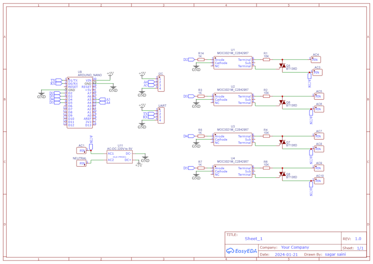
Here I choose D2, D3, D4 and D5 GPIOs of Arduino Nano to control with this module over voice commands, all the 4 GPIOs are connected to a solid state relay module and code is given below. Whenever a change in voice command are required then modify the following lines accordingly:
Serial.println(CMDID);
switch (CMDID) {

//relay1 for fan
case 75:                      // turn on the fan
digitalWrite(relay1, HIGH);
break;

case 76:                      // turn off the fan
digitalWrite(relay1, LOW);
break;
change the case statement code here 75 and 76 are for the Fan commands, if any custom commands are there then a unique code will be allotted to them. All the custom command words recording information can be founded in the previous getting started article.
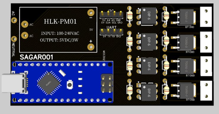
PCB designs:
The PCB is designed as per small load configuration, usually BT136 TRIAC can handle a max of 600v @4A of continuous current. Which is enough rating for a small load, but I will always recommend to use the PCB with loads below 300W. Because the TRIAC is mounted on the PCB itself, the heat dissipation capability is a little bit less.
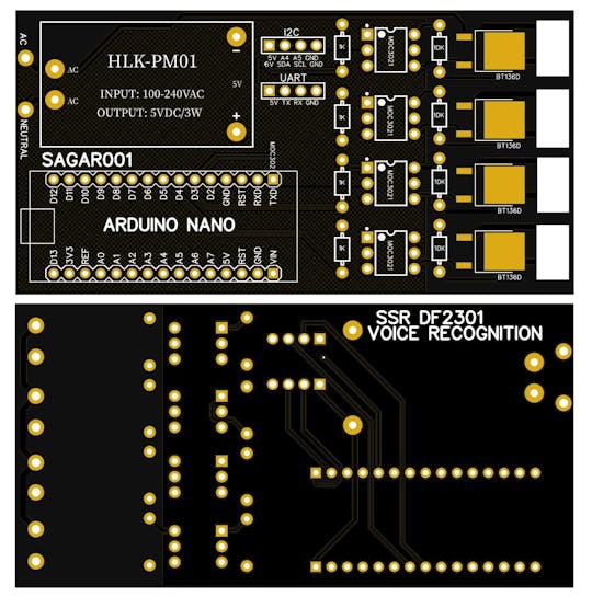
The Arduino and controlling section is placed one side and AC mains one side the design has an onboard 5v module which can be placed to power the Arduino and module. Pin headers are given for the offline module to connect over I2C or UART. This project contains AC power supply and handling with AC 220v is dangerous without proper knowledge of circuitry. Follow the below given diagram to connect any load to this PCB.
You can revolutionize your electronics projects with JLCPCB. A Chinese PCB (Printed Circuit Board) manufacturer that provides PCB fabrication and assembly services. Sign-up now using this link and get free PCB coupons for your next order. JLCPCB has over 10 years expertise in PCBA, SMT, Assembly, 3D printing, Stencil and CNC services.
Arduino Code for Relay:
Download all the required libraries, circuit and PCB from here.
#include "DFRobot_DF2301Q.h"
#define relay1 2 // relay is connected to the digital pin D2
#define relay2 3 // relay is connected to the digital pin D3
#define relay3 4 // relay is connected to the digital pin D4
#define relay4 5 // relay is connected to the digital pin D5
//I2C communication
DFRobot_DF2301Q_I2C asr; // activates the I2C mode of the voice recognition module
void setup() {
Serial.begin(115200);
pinMode(relay1, OUTPUT);    //Init relay pin to output mode
pinMode(relay2, OUTPUT);
pinMode(relay3, OUTPUT);
pinMode(relay4, OUTPUT);
digitalWrite(relay1, LOW);  //Set light pin to low
digitalWrite(relay2, LOW);
digitalWrite(relay3, LOW);
digitalWrite(relay4, LOW);
// Init the sensor
while (!(asr.begin())) {
Serial.println("Communication with device failed, please check connection");
delay(3000);
}
Serial.println("Begin ok!");
/**
* @brief Set voice volume
* @param voc - Volume value(1~7)
*/
asr.setVolume(7);
/**
@brief Set mute mode
@param mode - Mute mode; set value 1: mute, 0: unmute
*/
asr.setMuteMode(0);
/**
@brief Set wake-up duration
@param wakeTime - Wake-up duration (0-255)
*/
asr.setWakeTime(20);
/**
@brief Get wake-up duration
@return The currently-set wake-up period
*/
uint8_t wakeTime = 0;
wakeTime = asr.getWakeTime();
Serial.print("wakeTime = ");
Serial.println(wakeTime);
asr.playByCMDID(1);   // Wake-up command
/**
@brief Play the corresponding reply audio according to the ID
@param CMDID - command word ID
*/
//asr.playByCMDID(23);  // Command word ID
}
void loop() {
/**
@brief Get the ID corresponding to the command word
@return Return the obtained command word ID, returning 0 means no valid ID is obtained
*/
uint8_t CMDID = asr.getCMDID();
Serial.println(CMDID);
switch (CMDID) {
//relay1 for fan
case 75:   // turn on the fan
digitalWrite(relay1, HIGH);
break;
case 76:  // turn off the fan
digitalWrite(relay1, LOW);
break;
//relay2 for light
case 103:  // turn on the light
digitalWrite(relay2, HIGH);
break;
case 104: // turn off the light
digitalWrite(relay2, LOW);
break;
//relay3 for ac
//(max limit 100-200watt mini cooling system can run)
case 124:     // turn on ac
digitalWrite(relay3, HIGH);
break;
case 125:  // turn off ac
digitalWrite(relay3, LOW);
break;
//relay4 for mini home theater system
case 90:   // turn on the speaker
digitalWrite(relay4, HIGH);
break;
case 91:  // turn off the speaker
digitalWrite(relay4, LOW);
break;
default:
if (CMDID != 0) {
Serial.print("CMDID = ");  //Printing command ID
Serial.println(CMDID);
}
}
delay(300);
}
PCB connection with External Loads:
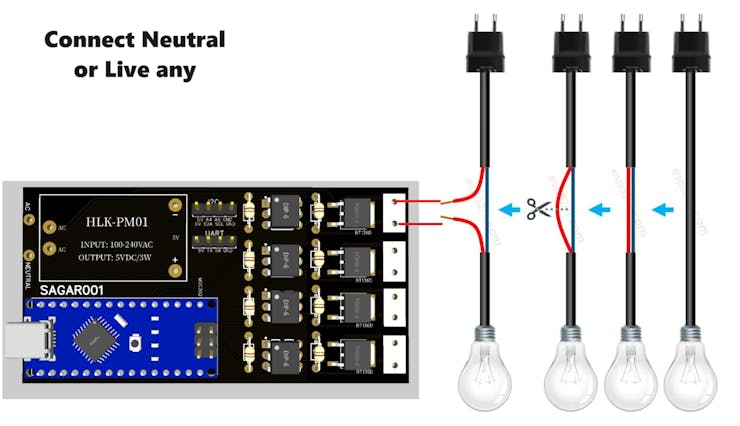
The external load connection is quite simple and same as a generic relay module, The solid state relay also works as the same, Just plug the neutral wire and whenever the voice command trigger that particular GPIO and the relay will make the connection. The above given circuit diagram can be followed to make the connections with load. Usually TRIAC based solid state relay is used to work with AC circuits.
Troubleshooting:
_GzGwMOHWQk.png?auto=compress%2Cformat&w=740&h=555&fit=max)
The PCB and circuit is tested, here I am using prebuilt commands but you can always change the configuration according to the recorded custom commands. DF2301 has onboard serial/I2C selection and keeps the button in I2C mode. Serial is not used here because Arduino only has one single serial port which is used to upload the programs via USB to TTL chip. If UART is used we are not able to print any values on the serial monitor. Which I think is a very crucial part in debugging when commands are not working. Always add one capacitor in between the power rails to reduce the noise while working with the breadboard. If the commands are not working at all delete all the commands and please choose a quiet environment to record again. Check JLCPCB now and get free coupons for your next order.
Custom parts and enclosures
Schematics
- TEST
Code
The article was first published in Hackster, January 24, 2024
cr: https://www.hackster.io/electroboy001/possible-smart-home-without-iot-7a9946
author: Electro BOY


