
Use a DFRobot MiniQ chassis with Raspberry Pi Zero W to create a robot that can shoot a laser at anything you choose! (Not at eyes, please.)
Things used in this project
Software apps and online services
Hand tools and fabrication machines
- Soldering iron (generic)
Story
Introduction
Ever wanted to make a robot? How about one that is controlled via Bluetooth? Still not exciting enough for you? This robot can fire lasers, basically becoming a mobile artillery piece that shoots light! Now you can tease your cat, make a presentation more exciting, and even shine it at people (just not at their eyes please)! This project will document how I went about creating a robot capable of such epic fun!
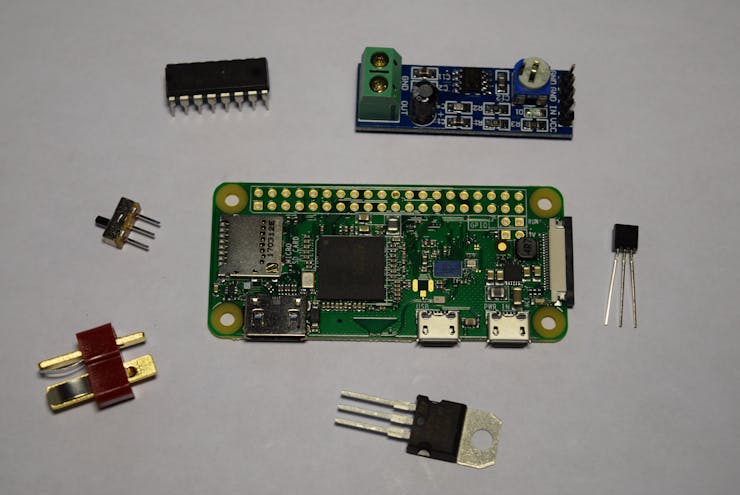
Parts Needed
DFRobot was generous to me by sending out a couple of their 2WD MiniQ Robot Chassis. These things are great! Each chassis came with 2 50:1 geared motors, nice sturdy tires, and plenty of mounting holes. Next, I got a Raspberry Pi Zero; it is small, yet very capable, due to its on board Wifi and Bluetooth. I also got an Arduino Nano and an HC-05 for the controller. See the BoM for the full list of parts needed.

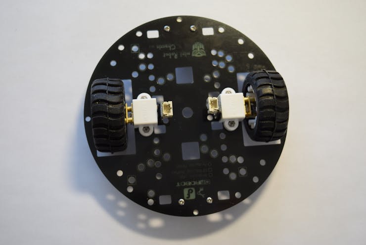
Assembly
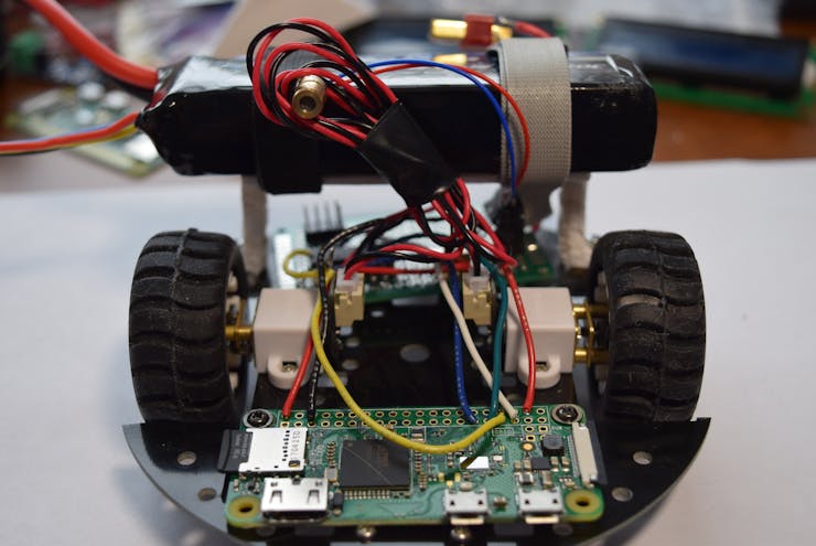
I began by assembling the 2WD MiniQ chassis kit from DFRobot. I slid the wheels onto the motor shafts, then inserted them into brackets and attached them to the chassis. Finally, I added the metal supports.
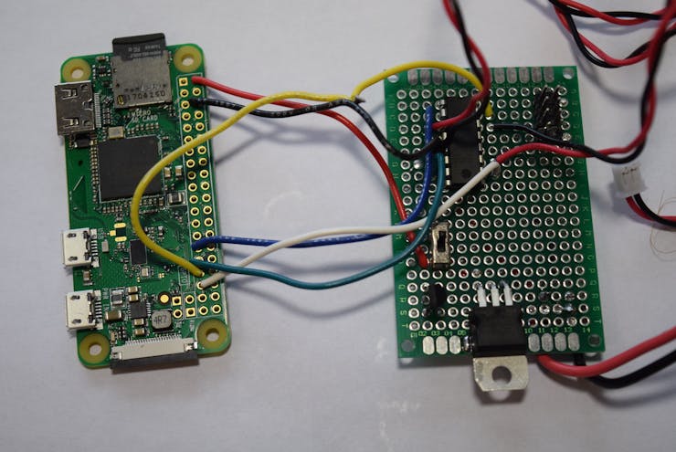
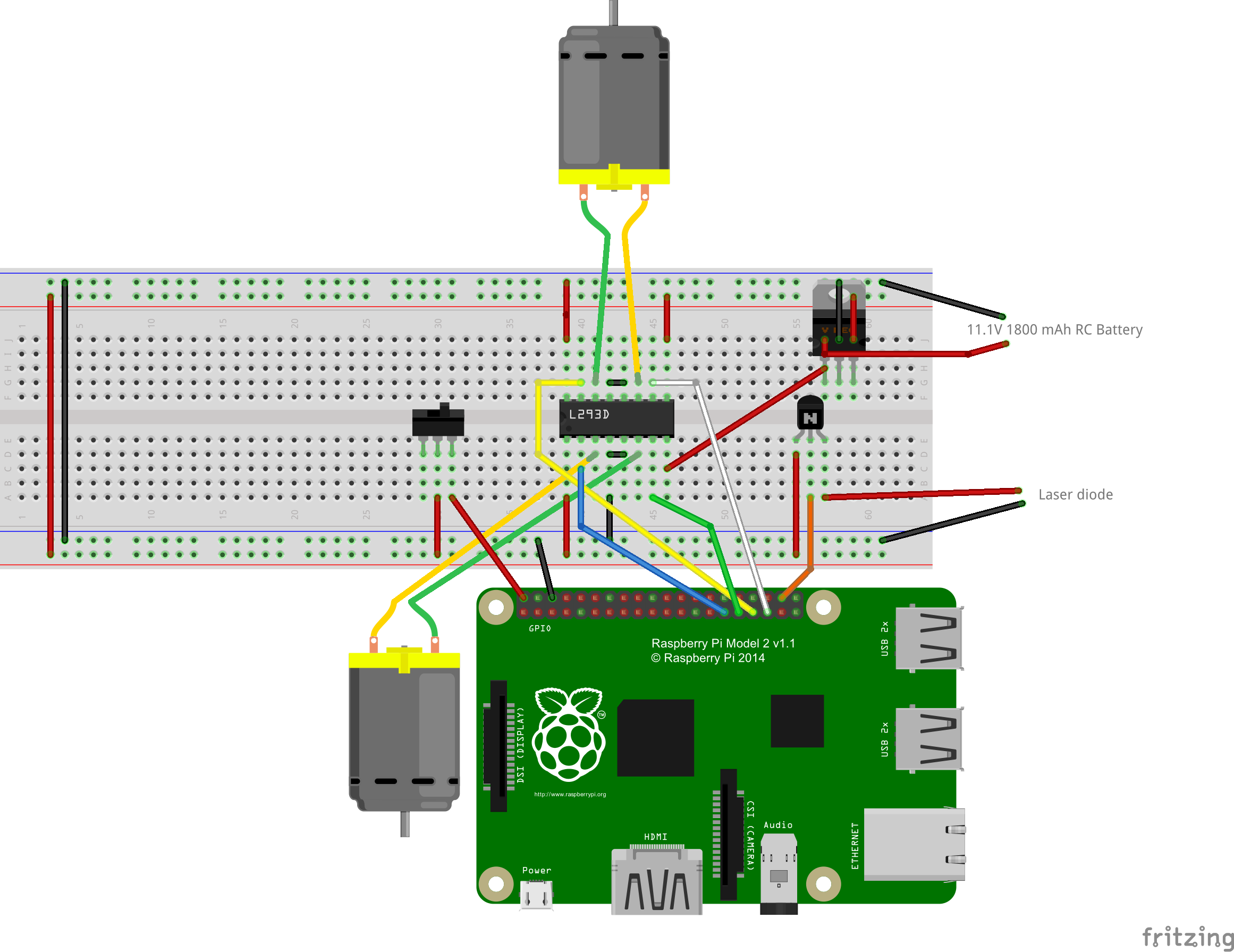
Now it was time to build the main board. The L293d motor driver got soldered in place, along with wires running to the Raspberry Pi's GPIO pins. Next, I soldered a connector for the battery, as that will provide the main power. After the power source was added, I installed a 5V regulator along with an NPN transistor. The regulator provides the right voltage for the Pi and laser diode, and the transistor allows the Pi to safely control the laser without blowing up.
Motor Control
This was actually one of the trickiest parts of this project. I had to decide the way I should transmit information to drive the wheels. I was faced with two options: tank or arcade drive. Tank drive operates like a.. tank, of course. Left makes right wheel go forwards and the left wheel goes backwards, turning the robot left. Here is a table for movements:
Joystick Position | Left Wheel | Right Wheel
Left | -1 | 1
Right | 1 | -1
Up | 1 | 1
Down | -1 | -1
Neutral | 0 | 0
But that gives you very limited control. Plus, when working with a large voltage, the robot tends to get zippy. A better option was to use PWM to variably control the motor speeds. Now, it isn't as simple as using an Arduino, there isn't any analogWrite(motor_pin, value) abstraction, which can get frustrating. Luckily, the RPi GPIO library has a PWM class. To use it, I first made each motor pin into an output with GPIO.setup(motor_pin, GPIO.OUT) . Then I made an object for each motor pin with motor_pwm = GPIO.PWM(motor_pin, 100) . Make sure to change the motor_pwm variable name for each object. Now that I had variable motor speeds, could focus on getting the values from the joystick translated into motor values.
The Controller
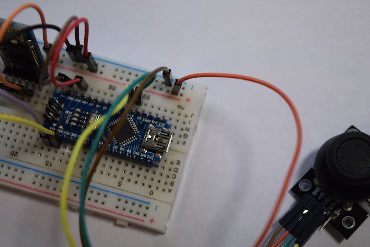
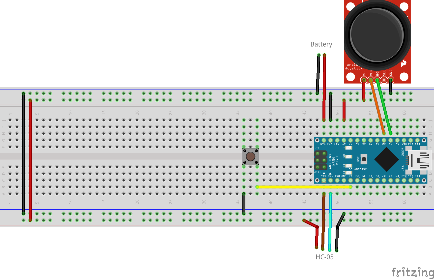
The basic analog joystick is made of two potentiometers that give a 10-bit value ranging from 0-1023 on the Arduino. I set up the Arduino Nano to take a reading from each analog pin that the joystick was connected to (in my case it was A1 and A2). After that, the code maps x and y to values between -50 and 50, like this:
int x = map(A1_reading, 0, 1023, -50, 50);
int y = map(A2_reading, 0, 1023, -50, 50);
Then, I added a constrain call to capture any outliers:
x = constrain(x, -100, 100);
y = constrain(y, -100, 100);
Sparkfun recently did a tutorial on how to use an RC controller for DC motors, which was perfect for what I needed. You can find that blog post here. The way to determine the way each motor goes is pretty simple. Just do:
int motor1 = x+y;
int motor2 = y-x;
And then:
motor1 = constrain(motor1, -100, 100);
motor2 = constrain(motor2, -100, 100);
...to ensure it stays within -100 and 100. And you may be asking, "How do I make it come to a stop?" Well, that is where a deadzone comes into play. By adding this as a global variable:
int deadzone = 10;...and then:
if(abs(motor1) <= deadzone){
   motor1 = 0;
 }
 if(abs(motor2) <= deadzone){
   motor2 = 0;
 }
...you can effectively stop a motor whenever you aren't pushing the joystick. Lastly, I was wondering how to efficiently send this motor data to the Raspberry Pi. It needed to be easily readable and have good decoding support. Then this idea popped into my head: JSON! I could send a string that conveys the motor data to the Pi, then the Pi can decode it into variables, and lastly control the motors accordingly. So I added these lines:
String json_string = "{\"motor\":[" + String(motor1)+","+String(motor2)+"]}";
  Serial.println(json_string);
which send the motor data as a JSON string, where "motor" is the key, and an array containing the motors values is its value. There is also an interrupt that will send "Fire" to the Pi if the button is pushed. Now for the last part: having fun with it!
Using the Robot
Before I began to use this new machine of light beams, I had to somehow get the HC-05 module talking to the Pi. Here is the condensed version. First, power on the HC-05 and Raspberry Pi, then click on the Bluetooth icon on the Raspberry Pi and pair your HC-05. The password should be: "1234" without the quotes.
On the Raspberry Pi Zero W, enter these commands:
hcitool scanThis will scan for bluetooth devices and return their MAC addresses. Now enter:
sudo rfcomm /dev/rfcomm0 mac_address...where mac_address is the address of the HC-05. Download the code for this project and transfer the Python files to a directory. REMEMBER THAT DIRECTORY; you will need it soon. Now open up the rc_car_main.py python script with a text editor, and where you see BT_addr , enter in "/dev/rfcomm0". Also, enter in the motor pins for the motors in:
car.config_motors(pin1, pin2, pin3, pin4, invert=False)Run the script and see if the robot moves the proper way. If it goes left when it should be going right, set invert=False to invert=True .
Have fun with your new laser firing bot!
Custom parts and enclosures
https://sketchfab.com/3d-models/battery-platform2-yscsqx6qlp-643f02f7be2f4f1f9f97c7c34b436db2
Schematics
Robot Schematic
Controller Schematic
Controller Code
int JS_VALS[2] = {};

const int button_pin = 2;
const int deadzone = 8;

void setup() {
  // put your setup code here, to run once:
Serial.begin(9600);
pinMode(button_pin, INPUT_PULLUP);
attachInterrupt(digitalPinToInterrupt(button_pin), fire_laser, FALLING);
}

void loop() {
  // put your main code here, to run repeatedly:
  JS_VALS[0] = analogRead(A1);
  JS_VALS[1] = analogRead(A2);
  int x = map(JS_VALS[0], 0, 1023, -50, 50);
  x = constrain(x, -100, 100);
  int y = map(JS_VALS[1], 0, 1023, -50, 50);
  y = constrain(y, -100, 100);
  int motor1 = x+y;
  int motor2 = y-x;
  motor1 = constrain(motor1, -100, 100);
  motor2 = constrain(motor2, -100, 100);
  if(abs(motor1) <= deadzone){
    motor1 = 0;
  }
  if(abs(motor2) <= deadzone){
    motor2 = 0;
  }
  //Serial.println("X: "+String(JS_VALS[0])+", Y: "+String(JS_VALS[1]));
  String json_string = "{\"motor\":[" + String(motor1)+","+String(motor2)+"]}";
  Serial.println(json_string);
  delay(30);
}

void fire_laser(){
  String json_string = "{\"shoot\":\"1\"}";
  Serial.println(json_string);
}
Python Robot Class
import RPi.GPIO as GPIO
from time import sleep
from serial import Serial
import json

class Car(object):

	def __init__(self, BT_Port, laser_pin):
		GPIO.setmode(GPIO.BCM)
		self.ser = Serial(BT_Port, baudrate=9600)
                self.laser_pin = laser_pin
                GPIO.setup(self.laser_pin, GPIO.OUT)

	def configMotors(self, mL1, mL2, mR1, mR2, invertLR=False):
	    self.motor_array = [mL1, mL2, mR1, mR2]
	    self.invert = invertLR
	    for pin in self.motor_array:
		GPIO.setup(pin, GPIO.OUT)
		#self.motor_pwm.append(GPIO.PWM(pin, 490))
	    self.motorL1_pwm = GPIO.PWM(mL1, 100)
	    self.motorL2_pwm = GPIO.PWM(mL2, 100)
	    self.motorR1_pwm = GPIO.PWM(mR1, 100)
	    self.motorR2_pwm = GPIO.PWM(mR2, 100)
	    self.motorL1_pwm.start(0)
	    self.motorL2_pwm.start(0)
	    self.motorR1_pwm.start(0)
	    self.motorR2_pwm.start(0)


	def receive_command(self):
            self.cmd = ""
            if self.ser.inWaiting():
                self.cmd = self.ser.readline()
                if self.cmd != None:
                    try:
                        data = self.cmd.decode('utf-8')
                        data = json.loads(data.strip())
                        print data
                        if data != "":
                            return data
                        else:
                            return ""
                    except ValueError:
                        pass

	def turn_wheel(self, motor1, motor2):
            if self.invert:
                temp = motor1
                motor1 = motor2
                motor2 = temp
            motor1 = (motor1 / 2)
            motor2 = (motor2 / 2)
            if motor1<0:
		self.motorL2_pwm.ChangeDutyCycle(motor1*-1)
		self.motorL1_pwm.ChangeDutyCycle(0)#make positive if negative
            else:
		self.motorL1_pwm.ChangeDutyCycle(motor1)
		self.motorL2_pwm.ChangeDutyCycle(0)

            if motor2<0:
		self.motorR2_pwm.ChangeDutyCycle(motor2*-1)
		self.motorR1_pwm.ChangeDutyCycle(0)#make positive if negative
            else:
		self.motorR1_pwm.ChangeDutyCycle(motor2)
		self.motorR2_pwm.ChangeDutyCycle(0)

        def fire_laser(self):
            GPIO.output(self.laser_pin, GPIO.HIGH)
            sleep(2)
            GPIO.output(self.laser_pin, GPIO.LOW)

	def update(self): #Run to make the robot work
            self.json_obj = self.receive_command()
	    print self.json_obj
	    try:
                if "motor" in self.cmd:
                    if self.json_obj["motor"] != None:
                   	 val1 = self.json_obj["motor"][0]
			# if val1 > 0:
      			 #    val1 += 10
                   	 val2 = self.json_obj["motor"][1]
			# if val2 <0:
			#	val2 += 4
                   	 self.turn_wheel(val1, val2)
		elif "shoot" in self.cmd:
		    self.fire_laser()
            except TypeError:
                pass
Python Robot Main Script (run this one)
import car

bt_port = "/dev/rfcomm0"
laser_pin = pin5
rc_car = car.Car(bt_port, laser_pin)

rc_car.configMotors(pin1,pin2,pin3,pin4, invertLR=False)

while 1:
    rc_car.update()
The article was first published in hackster, September 12, 2017
cr: https://www.hackster.io/gatoninja236/laser-shootin-robot-defad0
author: Arduino “having11” Guy


