
This is a IoT based environmental monitoring system for University Cafeteria.
Software apps and online services
· Arduino Web Editor
· Arduino IoT Cloud
· Arduino IDE
Hand tools and fabrication machines
· Soldering iron (generic)
· Solder Wire, Lead Free
Story
The negative effects of indoor air quality cause a decrease in the working efficiency of people, and health problems. For this reason, indoor air quality (IAQ) has been receiving more and more attention and increasing interest has been directed towards controlling of indoor particle concentration. There have been many studies reported on IAQ problems in different kinds of indoor environment but research on IAQ in university cafeteria is less documented. University cafeteria is a kind of building with unique characteristics: there are lots of people dining besides the large cooking area.
Maintaining good air quality can be a great challenge for the university cafeterias but it is very important. Before maintaining, monitoring the indoor air quality such as canteen, cafeteria and library is important in terms of quality of life.
In this project I will show how I made a device that will help to monitor air quality parameters like temperature, humidity, VOC, and noise level remotely in real-time. The data will be stored in the cloud for download and research. A graphical dashboard is also created for easy visualization.
Features of the Device
The device has the following features:
· Can measure temperature, humidity, VOC, illumination, and noise level· Remote monitoring· Real-time monitoring· Graphical dashboard· Smartphone compatible· Cloud Storage· Downloadable data· Battery Powered· Accurate
The Hardware
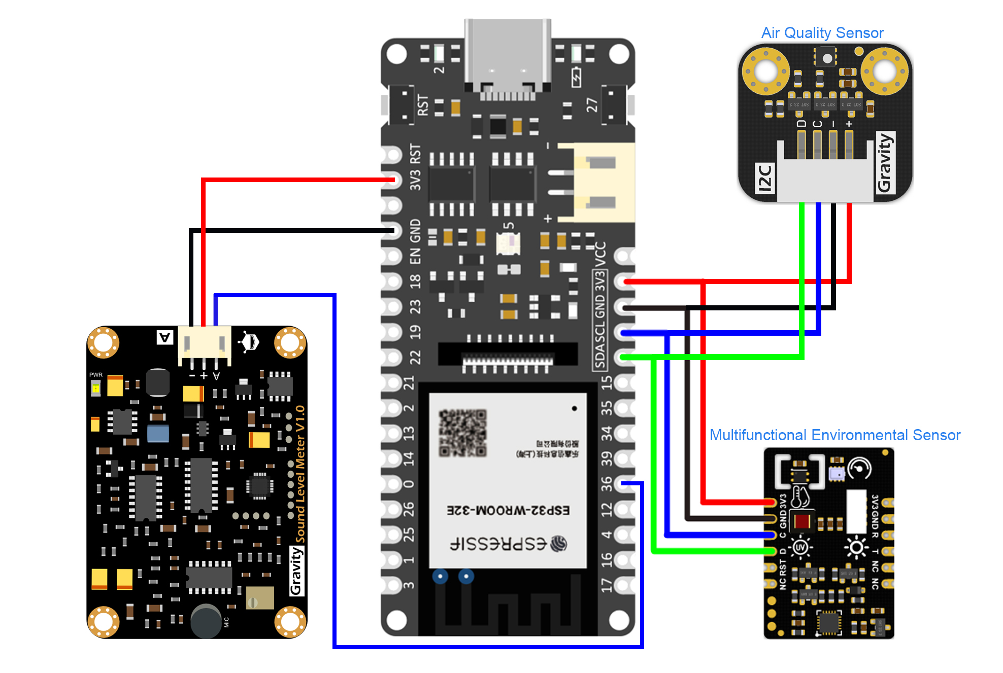
The following image shows the connections of the sensors with the Firebeetle board. I used here a DFRobot Analog Sound Level Meter which directly gives the noise level in dB form. The output of the sensor is analog and I connected A0 pin (pin #36) of the Firebeetle board to the output of the sensor.
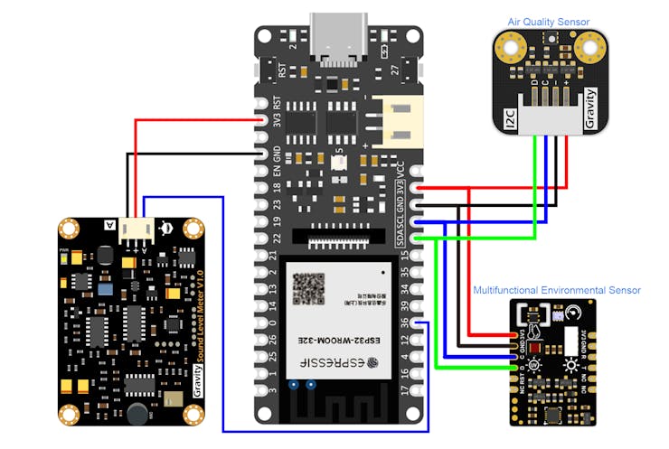
I also use a multifunctional environmental sensor for measuring environmental parameters. This multifunctional environmental sensor comprises SHTC3 temperature & humidity sensor, BMP280 atmospheric pressure sensor, VEML7700 light sensor, and LTR390 ultraviolet sensor (V1.0 : ML8511,V2.0 : LTR390-UV-01) into one and offers 5 kinds of environmental parameters.
The environmental sensor supports two communication methods, UART and I2C. I used I2C here for interfacing the sensor and connected with default CL and SDA pins.
For measuring air quality I used the SGP40 Air Quality sensor that adopts the new SGP40 digital VOC sensor chip launched by the well-known Sensirion. In combination with Sensirion’s powerful VOC algorithm, the sensor signal can be directly used to evaluate indoor air quality. It features low power(2.6mA), fast response(2s) and small body. The data from the sensor can be directly used to evaluate air quality without calibration. Integrated with easy-to-connect Gravity interface, this Gravity SGP40 Air Quality sensor is very suitable for indoor projects that will be used for a long time, such as refitting air purifiers, kitchen hoods, etc. Besides, we provide you with C and Python libraries for using with different main-controllers.
The sensor also use I2C interface. I connected this sensor with the same I2C pins used for the environmental sensor.
Following image shows the physical connections I made with the board.
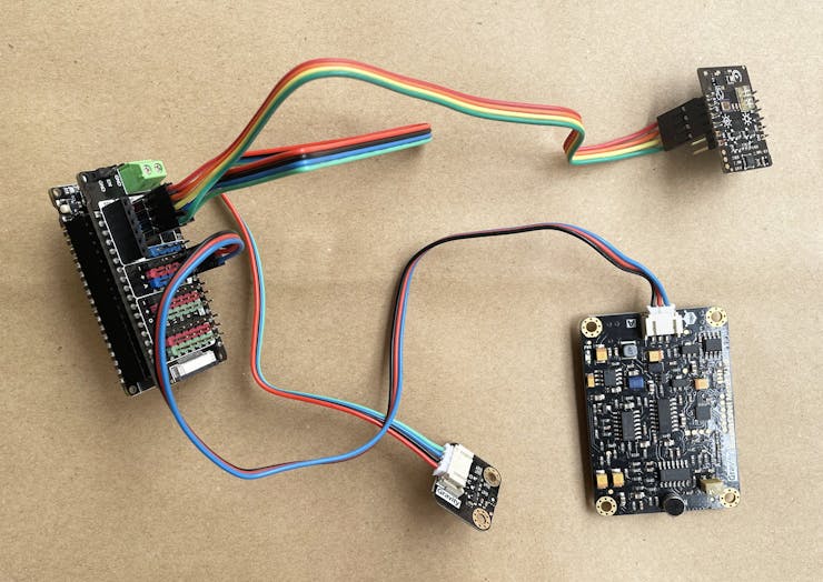
Placing Hardware Components inside a Box
I used 5mm PVC board to make a box for the hardware components. I attached the components to the bottom part of the box using double sided tape and duct tape.

Then I attached the outer pieces of the box using supper glue.

Finally, I placed the top part and attached with the supper glue. I made some hole to the top part that will allow the air and sound inside the box. I used a 400mAh Li-ion battery withe the FireBeetle board. The board has a built in i-ion charger so just attaching the micro USB cable to the board will charge the battery.
This is the placement of the final device.

How it Works
The following block diagram shows the working of the system. The brain of the system is a ESP32 based Firebeetle board from DFRobot. It collects the data from all the sensors and upload the data to Arduino IoT Cloud.

The cloud data can be vitalized remotely in real-time through graphical dashboard using web browser or smartphone. For cloud to device communication low power light weight MQTT protocol is used.
Cloud Configuration
For using Arduino IoT Cloud first login from the link https://cloud.arduino.cc/home/.This is a getting started guide you can follow to configure your cloud if you are new in Arduino Cloud. Following the guide I configure my Cloud as follows:

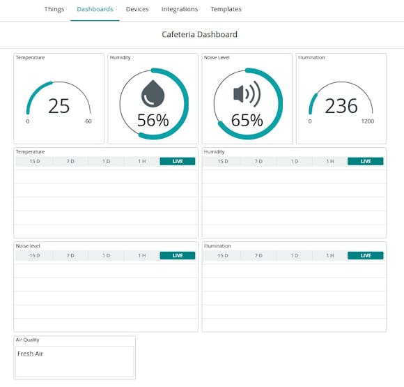
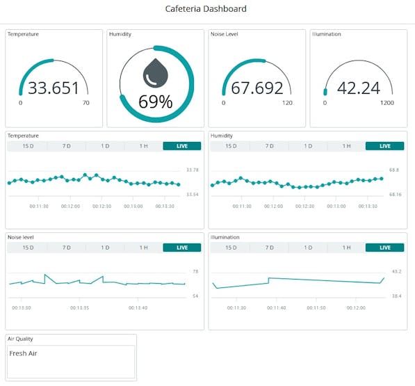
I have created five variables for five data parameters. For visualization of the data you must create a dashboard and link the widgets of the dashboard to the variables you created. The following screenshot shows my dashboard I have created fro this project.
Mobile view of the dashboard:


Writing Code
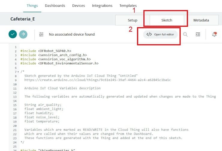
After completing the thing configuration on Arduino Cloud a template code will be automatically generated. You can open the code with the Arduino Web IDE by clicking Open full editor option.
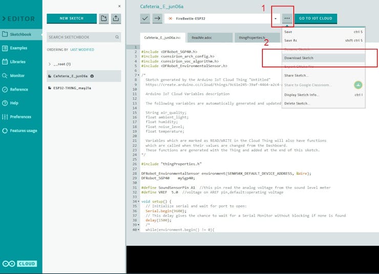
You can continue on Arduino Web IDE for developing the complete code or you can migrate to Arduino IDE by downloading the code from the online IDE.
In both cases you need to download the libraries for Gravity Air Quality Sensor and DFRobot Environmental Sensor.
· Download and install the SGP40 Library and Sample Code· Download and install the DFRobot_Environmental Sensor LibraryFor analog sound level meter you don't need to install any library. Just a simple analogRead( ) is required for reading the noise level from the sensor.
Sample code is here:
#define SoundSensorPin A1  //this pin read analog voltage from the sound level meter
#define VREF  3.3  //voltage on AREF pin,default:operating voltage

void setup()
{
    Serial.begin(115200);
}

void loop()
{
    float voltageValue,dbValue;
    voltageValue = analogRead(SoundSensorPin) / 4095.0 * VREF;
    dbValue = voltageValue * 50.0;  //convert voltage to decibel value
    Serial.print(dbValue,1);
    Serial.println(" dBA");
    delay(125);
}
After downloading the libraries you need to integrate the sensor reading functionality to the template code.
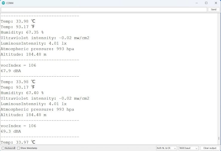
The full code is attached in the code section. The test data is printed to serial monitor. This confirmed that every sensor is working well.
After uploading the data to cloud the dashboard is look like follows:
Schematics
Schematic Diagram
This schematic shows the connections of the sensors with the DFRobot Firebeetle ESP32-E Board.
Complete Source Code
https://create.arduino.cc/editor/taifur/5e5c16d4-3f62-4e1b-a3ac-03c67f02467e/preview
The article was first published in hackster, June 6, 2023
cr: https://www.hackster.io/taifur/university-cafeteria-monitoring-system-44f6d3
author: Md. Khairul Alam


