This guide explains the steps to seamlessly integrate the WM1110 sensor module with The Things Network (TTN) and ThingSpeak for data transmission and visualization.
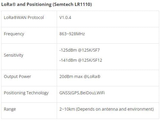
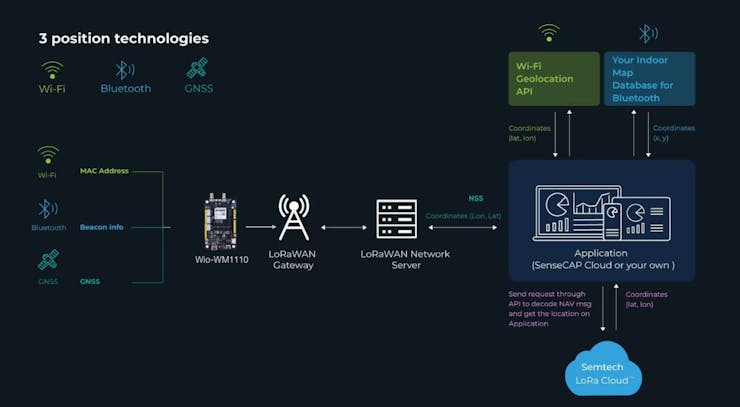
The seeed studio Wio-WM1110 Dev Kit is based on the Wio-WM1110 Wireless Module, which integrates both a Semtech LoRa® transceiver and a multi-purpose radio front-end for geolocation functionalities. The LoRa® transceiver enables low-power, high-sensitivity network coverage, while GNSS (GPS/BeiDou) and Wi-Fi scanning work together to offer comprehensive location coverage. Additionally, the Dev Kit provides connectivity options for a variety of peripherals, making it a versatile platform for developing diverse IoT applications.
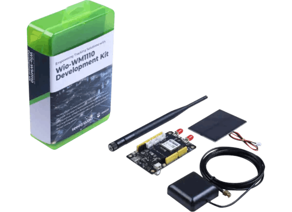
The Wio-WM1110 is a powerful fusion positioning module designed for developing low-power, long-range IoT applications. It combines the capabilities of the Semtech LR1110 LoRa transceiver and the Nordic nRF52840 microcontroller, offering a comprehensive solution for building connected devices with the following features:
Get PCBs for Your Projects Manufactured
This project was successfully completed because of the help and support from NextPCB. Guys if you have a PCB project, please visit their website and get exciting discounts and coupons.
NextPCB offers high-quality, reliable PCB starting at $1.9, and multilayer starting at $6.9. Also, everyone can enjoy free PCB assembly for 5 boards! Also, NextPCB is having a year end sale in which anyone can register through their website and get a $30 Coupon which can be used for ordering PCBs.
You can also try HQDFM free online PCB Gerber viewer to check your PCB design and avoid costly errors.
Let's learn what WM1110 is.
The Seeed Studio Wio-WM1110 is not just a blend of the Semtech LR1110 and Nordic nRF52840, it's a powerful fusion of these two technologies, creating a development platform with exceptional capabilities for building low-power, long-range IoT applications.
LR1110 Features
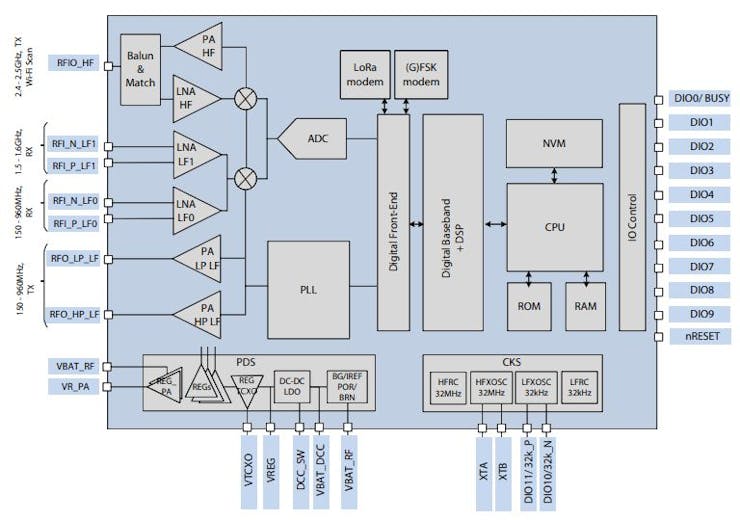
LR1110 Block diagram
Low-Power, High-Sensitivity LoRa®/(G)FSK Half-Duplex RF Transceiver
Supports worldwide ISM frequency bands in the range of 150 MHz to 960 MHz.Features a low-noise figure RX front-end for enhanced LoRa®/(G)FSK sensitivity.Offers two high-power PA paths: +22 dBm and +15 dBm, with a high-efficiency PA path at +15 dBm.Provides a long-range FHSS (LR-FHSS) modulator.Includes an integrated PA regulator supply selector for simplified dual power (+15 dBm/+22 dBm) implementation with one board design.Supports worldwide multi-region BoMs, with the circuit adapting to matching networks to satisfy regulatory limits.Fully compatible with SX1261/2/8 devices and the LoRaWAN® standard, defined by the LoRa Alliance®.Multi-Purpose Radio Front-End for Geolocation Applications
GNSS (GPS/BeiDou) low-power scanning802.11b/g/n Wi-Fi ultra-low-power passive scanning150 - 2700 MHz continuous frequency coverageHigh-bandwidth RX ADC (up to 24 MHz DSB)Digital baseband processingCryptographic Engine: Securing Your LoRaWAN Applications
The Wio-WM1110 integrates a powerful cryptographic engine to safeguard your LoRaWAN applications. Here's a breakdown of its key features:
Hardware-Accelerated Encryption/Decryption:
Provides efficient AES-128 encryption and decryption, crucial for securing data communication in LoRaWAN networks.Dedicated hardware offloads the processing burden from the main CPU, enhancing performance and reducing power consumption.Device Parameter Management:
Securely stores and manages device parameters like DevEUI and JoinEUI, defined by the LoRa Alliance.These unique identifiers are essential for device authentication and network access, and the cryptographic engine ensures their integrity and confidentiality.Enhanced Security:
Protects sensitive information like encryption keys from unauthorized access, preventing potential breaches and data leaks.Offers a secure environment for storing critical data like NwkKey and AppKey, as defined in the LoRaWAN standard.Overall, the cryptographic engine plays a crucial role in safeguarding the security and reliability of your LoRaWAN applications. It provides comprehensive protection for sensitive data and facilitates secure communication within the network.
NRF52840 Features
The NRF52840 is a powerful and versatile Bluetooth Low Energy (BLE) SoC from Nordic Semiconductor, offering a wide range of features for various IoT applications. Here's a breakdown of its key highlights:
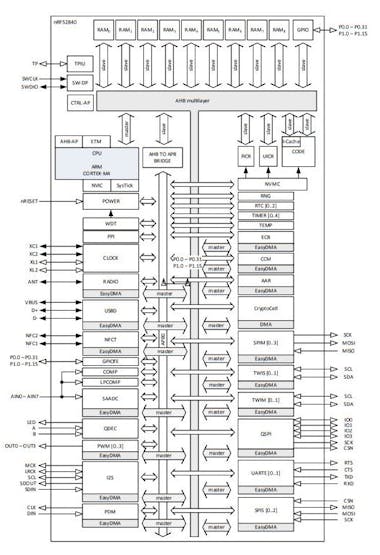
NRF52840 Block Diagram
CPU and Memory:
64 MHz Arm Cortex-M4F CPU with FPU: Delivers ample processing power for running complex applications.1 MB Flash memory: Stores application code and data.256 KB RAM: Provides sufficient memory for application execution and data handling.Wireless Connectivity:
Bluetooth 5.3: Supports the latest Bluetooth standard for long-range, high throughput, and improved security.2 Mbps PHY: Enables faster data transfer compared to previous Bluetooth versions.Long Range: Achieves extended communication range for IoT applications.802.15.4: Supports additional protocols like Thread and Zigbee for wider ecosystem compatibility.Peripherals and Interfaces:
Multiple GPIOs: Enables connection to various sensors, actuators, and peripherals.High-speed SPI and QSPI: Offers fast data transfer for external memory and displays.PDM and I2S: Supports digital microphones and audio applications.Full-speed USB device: Enables data transfer and battery charging.ADC and DAC: Allows analog signal acquisition and generation.Power Management:
Ultra-low power consumption: Enables long battery life for IoT devices.Multiple power saving modes: Dynamically adjusts power consumption based on application requirements.Security:
Hardware Cryptographic Engine: Provides secure data encryption and decryption.Secure Boot: Ensures only authorized code can be executed on the device.Other Features:
Real-time clock (RTC): Enables accurate timekeeping.Temperature sensor: Provides temperature readings for environmental monitoring.On-chip debugger: Simplifies development and debugging process.Open-source platform:
Access to extensive resources and libraries for easier development and customization.Overall, the NRF52840 is a powerful and feature-rich SoC that empowers developers to build innovative and efficient IoT solutions with low power consumption and robust capabilities.
Wio-WM1110 Dev Kit Block Diagram & Hardware Overview
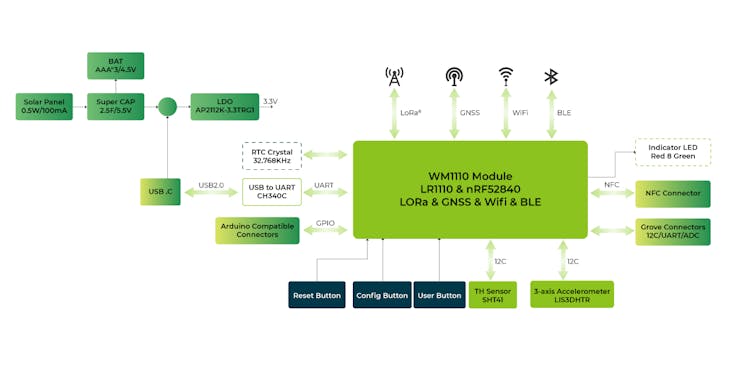
Wio-WM1110 Dev Kit Block Diagram
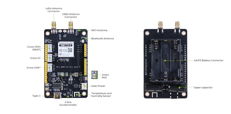
Hardware Overview
Pinout
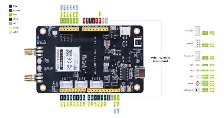
Pin Diagram
Specifications
1 / 3
Firmware Development for Wio-WM1110
Before we begin developing, we will need the following tools to complete this Getting Started Guide.
Preparation
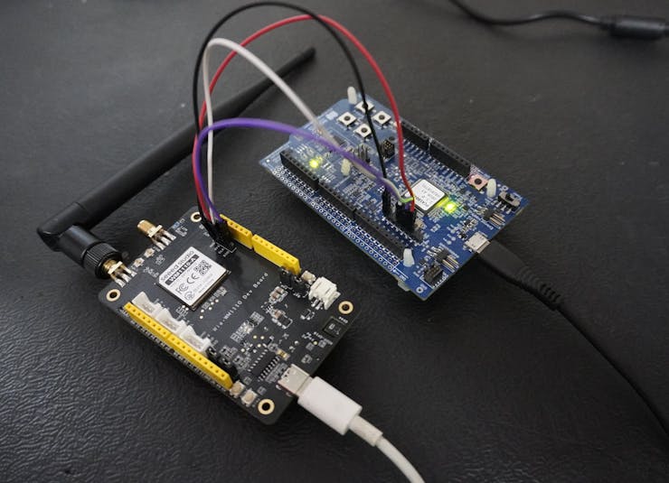
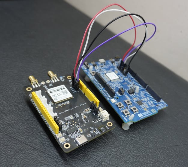
Wio-WM1110 Dev Kit x 1Computer x 1USB Type-C Cable x 1USB Type-B Cable x 1J-Link Debug Programmer(or nRF52dk) x 1Power on the Wio-WM1110 Dev Board and connect the J-Link Debug Programmer to the board as follows:
Connect the nRF52 DK's J-Link SWD pins (SWDIO and SWCLK) to the Wio-WM1110 Dev Board's SWD pins (SWDIO and SWCLK) to flash the firmware
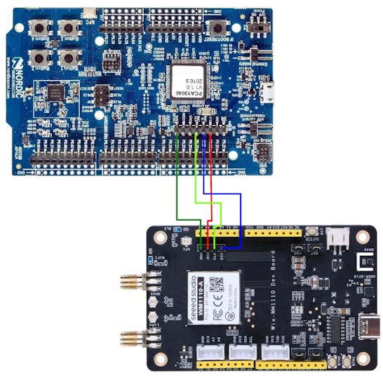
CONNECTION:
3V3 (Wio-WM1110 Dev Board) -> VTG (J-Link Debug Programmer nrf52dk)CLK (Wio-WM1110 Dev Board) -> SWCLK (J-Link Debug Programmer nrf52dk)DIO (Wio-WM1110 Dev Board) -> SWDIO (J-Link Debug Programmer nrf52dk)GND (Wio-WM1110 Dev Board) -> GND (J-Link Debug Programmer nrf52dk)
Programming Software:
A variety of programming software options exist for developing firmware on the WM1110. I have tested the module using Arduino IDE, PlatformIO, Keil uVision, Visual Studio Code, SEGGER Embedded Studio (SES), and Mbed Studio. From my experience, Mbed Studio and SEGGER Embedded Studio (SES) offer the most user-friendly experience for firmware development. This Getting Started guide will utilize SEGGER Embedded Studio (SES) for developing the firmware.
SEGGER Embedded Studio (SES) is a comprehensive and user-friendly IDE for managing, building, testing, and deploying embedded applications. This translates to smooth and efficient development operations thanks to its extensive feature set.
Powerful Project Management: Effortlessly manage your Wio-WM1110 firmware projects, regardless of size or complexity, with SES's robust project management tools.Seamless Version Control: Leverage built-in version control features to track changes and deploy applications automatically.Integrated Build and Debugging Tools: Utilize SES's powerful integrated build and debugging tools to streamline your Wio-WM1110 firmware development workflow.Installing SEGGER Embedded Studio :
The software can be downloaded from this link: It's recommended to use the 5.68 version.https://www.segger.com/downloads/embedded-studio/
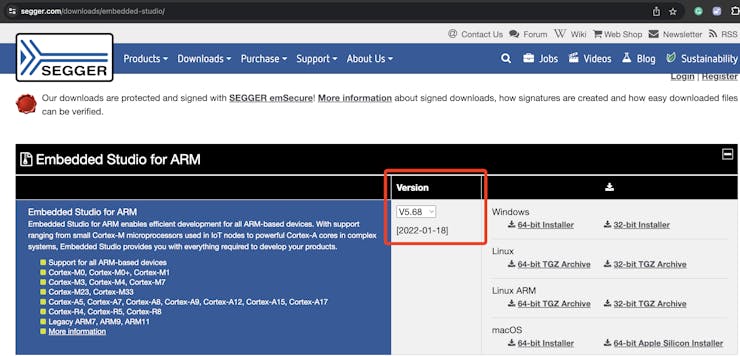
Download the nRF5 SDK and place it in the same directory where SEGGER Embedded Studio is installed.
The nRF5 SDK provides a comprehensive development environment for nRF5 Series devices. It includes a broad selection of drivers, libraries, examples for peripherals, SoftDevices, and proprietary radio protocols. All code examples within the SDK are specifically designed to compile and run on the Wio-WM1110 Dev Kit, streamlining your development process.
The software can be downloaded from this link: nRF5 SDK-Download
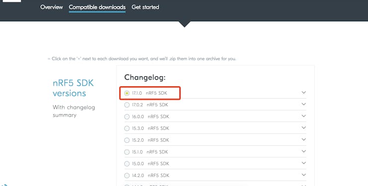
Download the Seeed Example Package and place it in the same directory where the nRF5 SDK is installed.
The Seeed Example Package can be downloaded from this link:Seeed Example-Download
Seeed Studio provides an example project to jumpstart developers' progress. This project encompasses LoRaWAN communication, positioning information acquisition, onboard sensor data acquisition, and more.
Add Seeed Example file to nRF5 SDK
Copy the Seeed Example file to the following path of nRF5 SDK: .../nRF5_SDK_17.1.0_ddde560/examples/peripheral/
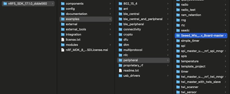
Testing the Wio-WM1110's Onboard LED with a Blinky Example
The Blinky Example code is readily available within the "Example" folder. Access the code by navigating to the "Open solution" tab.
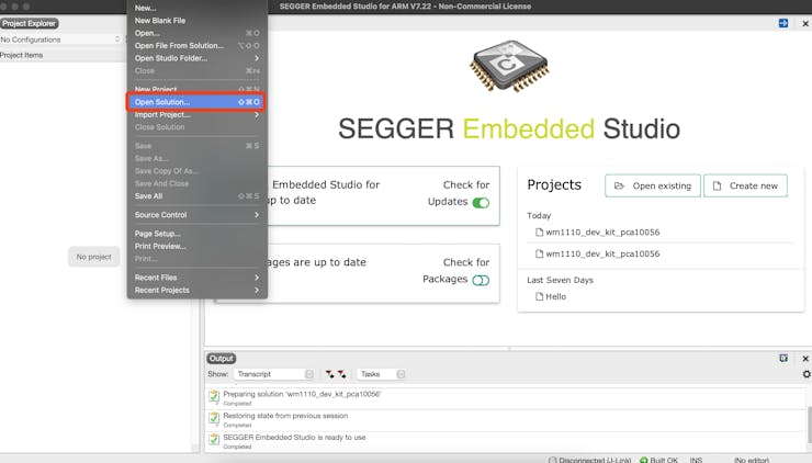
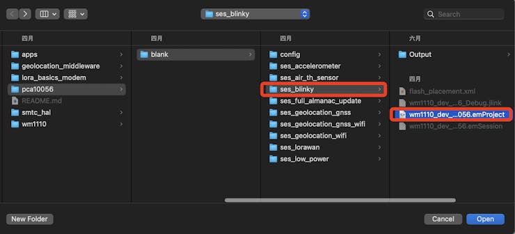
Compiling the test application
Select "Build" > "Compile project_target".
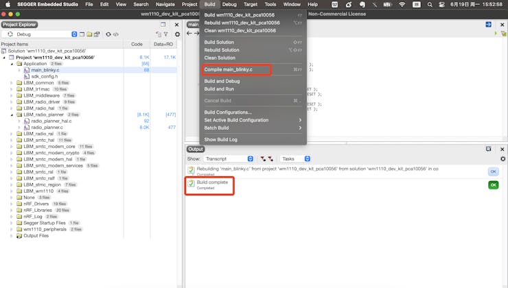
Programming the test application
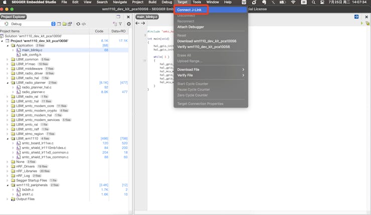
After compiling the application, you can program it to the Dev board.
Click "Target" -- "Connect J-Link"
Click "Build" -- "Build and Run" to build the blinky project.
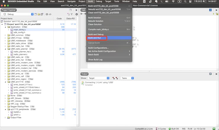
You will see "Download successful" when it has been completed.
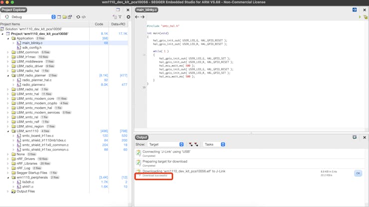
Then the 2 LEDs on the board will blink as follows.
Example code for Seamless Integration of WM1110 using TTN and ThingSpeak.
In this project, the onboard temperature and humidity sensors of the WM1110 development kit are used to collect data. This sensor data is sent to ThingSpeak for data transmission and visualization, utilizing TTN webhooks integration.
Before diving straight into LoRaWAN integration, we need to learn the LR1110's instructions to integrate it with the code. Otherwise, it won't be easy to understand the code.
First, learn about LoRaWAN from the Semtech Learning Center. Here is the link to the courses: https://learn.semtech.com/
Next, go through the LoRa Basics™ Modem User Manual for comprehensive instructions on handling the LoRaWAN protocol.
Setup the LoRaWAN Configuration keys
Wio-WM1110 DK allows users to set the DevEUI, AppEUI, and AppKey, so you can set up our parameters in the 'lorawan_key_config.h' file
Based on the operating region, you must specify the LORAWAN_REGION. The AppEUI key is user-defined and requires manual entry during registration.
_sdlAgEjtXo.png?auto=compress%2Cformat&w=740&h=555&fit=max)
In the current example project, I have manually entered the AppEUI key.
Device Registering on LoRaWAN® Network Server(TTN)
To begin, register for an account with The Things Industries or The Things Network.
Step 1: Create an application
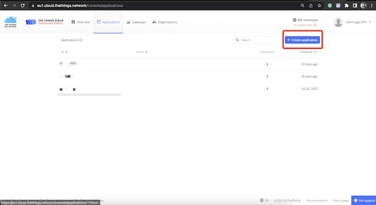
Navigate to the Applications page, and click "+Create application".
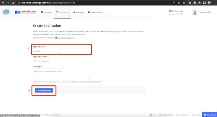
Enter an application ID in lowercase letters and numbers only. You may also use the hyphen (-) symbol. Click Create Application to save your changes.
Step 2: Register the Device
Click "Register end device".
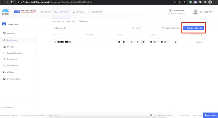
Set the following parameters:
Frequency Plan: Select the appropriate Frequency plan for the target region
LoRaWAN version:LoRaWAN Specification 1.0.3
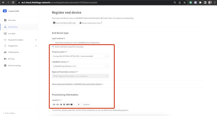
The remaining keys, DevEUI and AppKey, can be generated using automated tools.
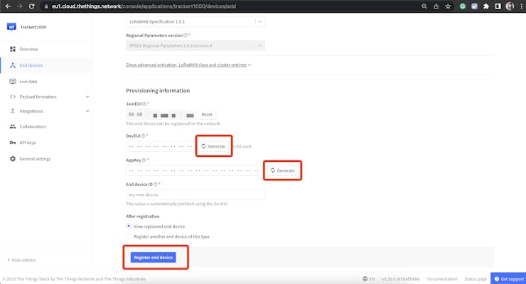
Here are the actual settings that I specifically configured for the current example project.
_8grwgtgOot.png?auto=compress%2Cformat&w=740&h=555&fit=max)
For a better understanding of how to integrate the whole process, please follow the video provided below.
CODE:
#include "main_lorawan.h"
#include "lorawan_key_config.h"
#include "smtc_board.h"
#include "smtc_hal.h"
#include "apps_modem_common.h"
#include "apps_modem_event.h"
#include "smtc_modem_api.h"
#include "device_management_defs.h"
#include "smtc_board_ralf.h"
#include "apps_utilities.h"
#include "smtc_modem_utilities.h"

float temp = 0, humi = 0;
#define xstr( a ) str( a )
#define str( a ) #a

static uint8_t stack_id = 0;
static uint8_t app_data_buffer[LORAWAN_APP_DATA_MAX_SIZE];
static void send_frame( const uint8_t* buffer, const uint8_t length, const bool confirmed );
static void parse_downlink_frame( uint8_t port, const uint8_t* payload, uint8_t size );
static void on_modem_reset( uint16_t reset_count );
static void on_modem_network_joined( void );
static void on_modem_alarm( void );
static void on_modem_tx_done( smtc_modem_event_txdone_status_t status );
static void on_modem_down_data( int8_t rssi, int8_t snr, smtc_modem_event_downdata_window_t rx_window, uint8_t port,
                                const uint8_t* payload, uint8_t size );

int main( void )
{
hal_debug_init( );
    hal_i2c_master_init( );
    hal_gpio_init_out( SENSOR_POWER, HAL_GPIO_SET );
    hal_mcu_wait_ms( 10 ); // wait power on
    SHT41Init( );
    static apps_modem_event_callback_t smtc_event_callback = {
        .adr_mobile_to_static  = NULL,
        .alarm                 = on_modem_alarm,
        .almanac_update        = NULL,
        .down_data             = on_modem_down_data,
        .join_fail             = NULL,
        .joined                = on_modem_network_joined,
        .link_status           = NULL,
        .mute                  = NULL,
        .new_link_adr          = NULL,
        .reset                 = on_modem_reset,
        .set_conf              = NULL,
        .stream_done           = NULL,
        .time_updated_alc_sync = NULL,
        .tx_done               = on_modem_tx_done,
        .upload_done           = NULL,
    };

    /* Initialise the ralf_t object corresponding to the board */
    ralf_t* modem_radio = smtc_board_initialise_and_get_ralf( );

    /* Disable IRQ to avoid unwanted behaviour during init */
    hal_mcu_disable_irq( );

    /* Init board and peripherals */
    hal_mcu_init( );
    smtc_board_init_periph( );

    /* Init the Lora Basics Modem event callbacks */
    apps_modem_event_init( &smtc_event_callback );

    /* Init the modem and use apps_modem_event_process as event callback, please note that the callback will be called
     * immediately after the first call to modem_run_engine because of the reset detection */
    smtc_modem_init( modem_radio, &apps_modem_event_process );

    /* Re-enable IRQ */
    hal_mcu_enable_irq( );

    HAL_DBG_TRACE_MSG( "\n" );
    HAL_DBG_TRACE_INFO( "###### ===== LoRa Basics Modem LoRaWAN Class A/C demo application ==== ######\n\n" );

    /* LoRa Basics Modem Version */
    apps_modem_common_display_lbm_version( );

    /* Configure the partial low power mode */
    hal_mcu_partial_sleep_enable( APP_PARTIAL_SLEEP );

    while( 1 )
    {
        /* Execute modem runtime, this function must be called again in sleep_time_ms milliseconds or sooner. */
        uint32_t sleep_time_ms = smtc_modem_run_engine( );

        SHT41GetTempAndHumi( &temp, &humi );
//HAL_DBG_TRACE_INFO( "temp = %.1f, humi = %.1f\r\n", temp, humi );

        hal_mcu_set_sleep_for_ms( sleep_time_ms );
    }
}


static void on_modem_reset( uint16_t reset_count )
{
    HAL_DBG_TRACE_INFO( "Application parameters:\n" );
    HAL_DBG_TRACE_INFO( "  - LoRaWAN uplink Fport = %d\n", LORAWAN_APP_PORT );
    HAL_DBG_TRACE_INFO( "  - DM report interval   = %d\n", APP_TX_DUTYCYCLE );
    HAL_DBG_TRACE_INFO( "  - Confirmed uplink     = %s\n", ( LORAWAN_CONFIRMED_MSG_ON == true ) ? "Yes" : "No" );

    apps_modem_common_configure_lorawan_params( stack_id );

    ASSERT_SMTC_MODEM_RC( smtc_modem_join_network( stack_id ) );
}

static void on_modem_network_joined( void )
{
    ASSERT_SMTC_MODEM_RC( smtc_modem_alarm_start_timer( APP_TX_DUTYCYCLE ) );

    ASSERT_SMTC_MODEM_RC( smtc_modem_adr_set_profile( stack_id, LORAWAN_DEFAULT_DATARATE, adr_custom_list ) );
}

static void on_modem_alarm( void )
{
    smtc_modem_status_mask_t modem_status;
    uint32_t                 charge        = 0;
    uint8_t                  app_data_size = 0;

    /* Schedule next packet transmission */
    ASSERT_SMTC_MODEM_RC( smtc_modem_alarm_start_timer( APP_TX_DUTYCYCLE ) );
    HAL_DBG_TRACE_PRINTF( "smtc_modem_alarm_start_timer: %d s\n\n", APP_TX_DUTYCYCLE );

    ASSERT_SMTC_MODEM_RC( smtc_modem_get_status( stack_id, &modem_status ) );
    modem_status_to_string( modem_status );

    app_data_buffer[app_data_size++] = temp;
    app_data_buffer[app_data_size++] = humi;


    send_frame( app_data_buffer, app_data_size, LORAWAN_CONFIRMED_MSG_ON );
}

static void on_modem_tx_done( smtc_modem_event_txdone_status_t status )
{
    static uint32_t uplink_count = 0;

    HAL_DBG_TRACE_INFO( "Uplink count: %d\n", ++uplink_count );
}

static void on_modem_down_data( int8_t rssi, int8_t snr, smtc_modem_event_downdata_window_t rx_window, uint8_t port,
                                const uint8_t* payload, uint8_t size )
{
    HAL_DBG_TRACE_INFO( "Downlink received:\n" );
    HAL_DBG_TRACE_INFO( "  - LoRaWAN Fport = %d\n", port );
    HAL_DBG_TRACE_INFO( "  - Payload size  = %d\n", size );
    HAL_DBG_TRACE_INFO( "  - RSSI          = %d dBm\n", rssi - 64 );
    HAL_DBG_TRACE_INFO( "  - SNR           = %d dB\n", snr >> 2 );

    switch( rx_window )
    {
    case SMTC_MODEM_EVENT_DOWNDATA_WINDOW_RX1:
    {
        HAL_DBG_TRACE_INFO( "  - Rx window     = %s\n", xstr( SMTC_MODEM_EVENT_DOWNDATA_WINDOW_RX1 ) );
        break;
    }
    case SMTC_MODEM_EVENT_DOWNDATA_WINDOW_RX2:
    {
        HAL_DBG_TRACE_INFO( "  - Rx window     = %s\n", xstr( SMTC_MODEM_EVENT_DOWNDATA_WINDOW_RX2 ) );
        break;
    }
    case SMTC_MODEM_EVENT_DOWNDATA_WINDOW_RXC:
    {
        HAL_DBG_TRACE_INFO( "  - Rx window     = %s\n", xstr( SMTC_MODEM_EVENT_DOWNDATA_WINDOW_RXC ) );
        break;
    }
    }

    if( size != 0 )
    {
        HAL_DBG_TRACE_ARRAY( "Payload", payload, size );
    }
}

static void send_frame( const uint8_t* buffer, const uint8_t length, bool tx_confirmed )
{
    uint8_t tx_max_payload;
    int32_t duty_cycle;

    /* Check if duty cycle is available */
    ASSERT_SMTC_MODEM_RC( smtc_modem_get_duty_cycle_status( &duty_cycle ) );
    if( duty_cycle < 0 )
    {
        HAL_DBG_TRACE_WARNING( "Duty-cycle limitation - next possible uplink in %d ms \n\n", duty_cycle );
        return;
    }

    ASSERT_SMTC_MODEM_RC( smtc_modem_get_next_tx_max_payload( stack_id, &tx_max_payload ) );
    if( length > tx_max_payload )
    {
        HAL_DBG_TRACE_WARNING( "Not enough space in buffer - send empty uplink to flush MAC commands \n" );
        ASSERT_SMTC_MODEM_RC( smtc_modem_request_empty_uplink( stack_id, true, LORAWAN_APP_PORT, tx_confirmed ) );
    }
    else
    {
        HAL_DBG_TRACE_INFO( "Request uplink\n" );
        ASSERT_SMTC_MODEM_RC( smtc_modem_request_uplink( stack_id, LORAWAN_APP_PORT, tx_confirmed, buffer, length ) );
    }
}

/* --- EOF ------------------------------------------------------------------ */


