
To date, my workshop robots projects have been driven toward low-cost and ease of assembly. What if performance and accuracy were the goals, and not cost? What if a robot kit company was willing to donate parts? And what if we drew with something other than markers?
So, the goal of this project is to make an accurate Turtle Robot using off the shelf parts that will draw something interesting for the next Maker Fair.
Turtles Away!
DEMO
Step 1: Parts
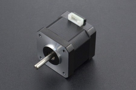
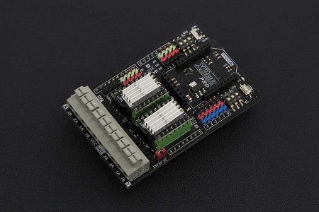
DFRobot provided the main components. Here is what we are using:
For power, I'm going to use 18650 Lithium cells, so I bought:
- 3 ea., EBL 18650 Battery 3.7V
- 1 ea., KINDEN 18650 Smart Battery Charger
- 3 ea., 18650 Battery Holder
I also used some various hardware:
- 2 ea., Buna-N Rubber #343 O-Ring (3/16" x 3-3/4" ID)
- 1 ea., 1" low-carbon steel ball bearing
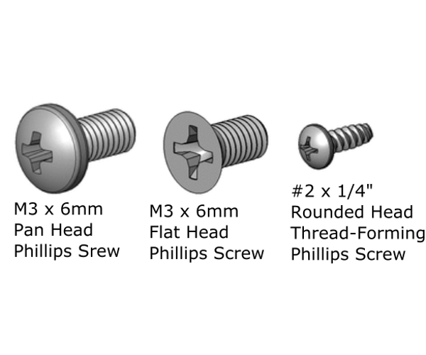
- 10 ea., M3x6MM Pan head screw
- 2 ea., M3x8MM Pan head screw
- 4 ea., M3x6MM Flathead screw
- 14 ea., M3 nut
- 4 ea., #2 x 1/4 thread-forming screw
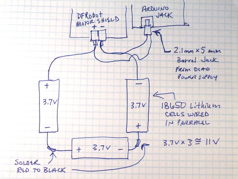
We are also going to need a creative way to share battery power between the Motor Shield and the Arduino since there doesn't seem to accommodations for that. I used the 2.1mm x 5mm barrel jack end of a dead power supply, or something like this.
Tools:
- Phillips tip screw driver
- Wire strippers
- Hot glue gun (optional)
- Soldering iron & solder
And not the least of which:
- Patience
- Persistance
- Positive Attitude
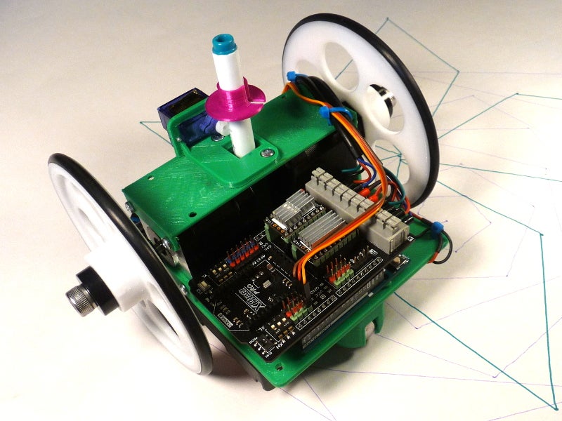
Step 2: 3D Parts
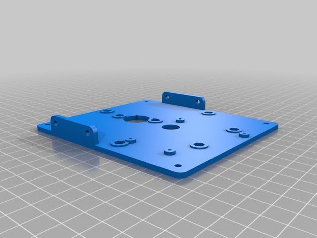
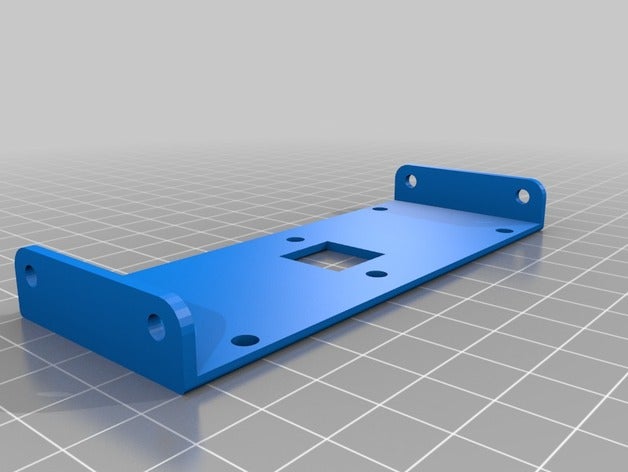
I decided to try and design all the 3D in FreeCad for this robot to help me learn. All I needed to do was transfer dimensions for the servo and pen arrangement, and then scale the remainder up to fit the much larger steppers.
- Larger wheels to provide clearance for the batteries.
- Thicker chassis to provide strength for the increased weight.
- Larger caster to match the raised deck height.
- Modular for easy testing and customization.
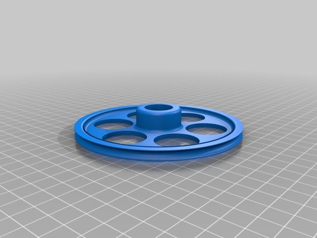
Here are the pieces you will need. All files are housed at https://www.thingiverse.com/thing:2976527
- 1 ea., chassis
- 1 ea., top strut
- 2 ea., wheel
- 1 ea., barrel
- 1 ea., servo holder
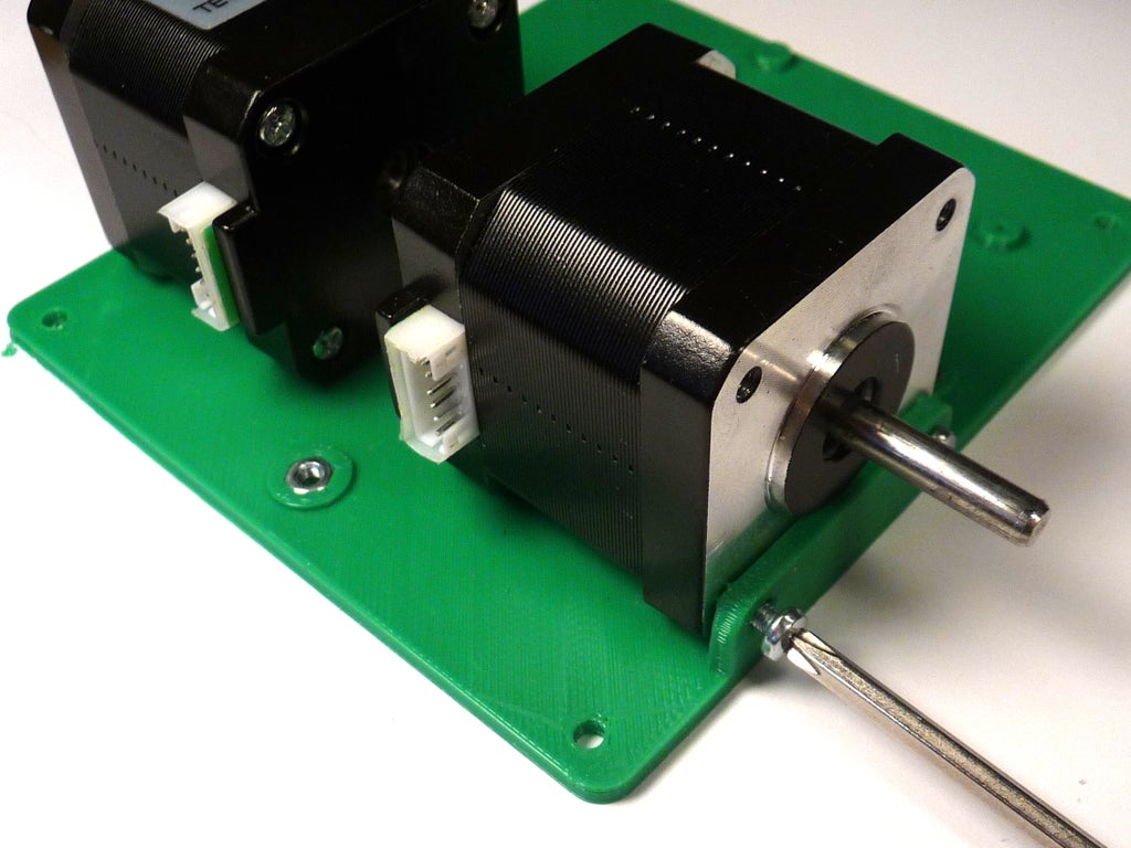
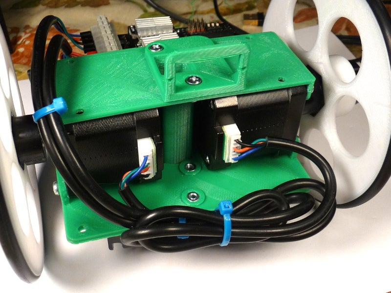
Step 3: Chassis Assembly Part 1
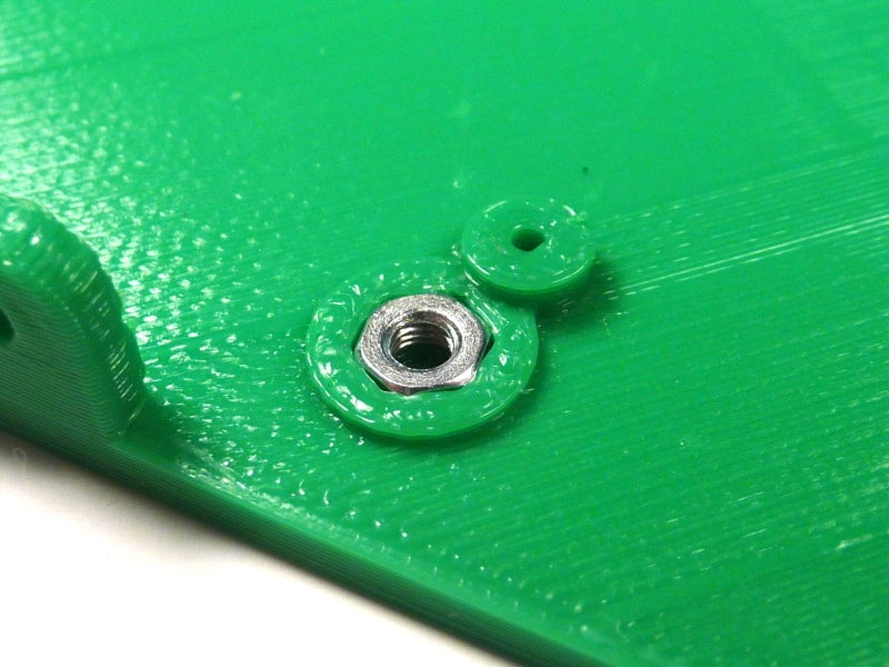
- Start by inserting M3 nuts in the chassis standoffs. They can either be pressed in, or pulled in using a M3 screw.
- Mount the steppers with M3 screws with the electrical connectors facing the back (shorter) end.
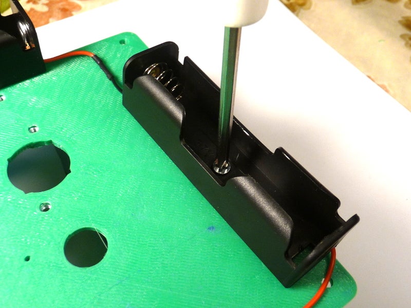
- Mount the battery holders using flat-head screws.
Step 4: Chassis Assembly Part 2
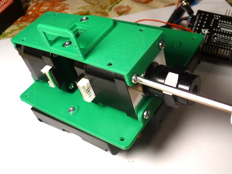
- Mount the barrel, top piece, and servo together with M3 screws and nuts.
- Mount the combined top piece to the steppers with M3 screws.
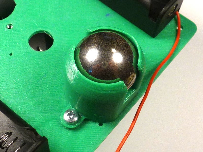
- Insert the steel bearing into the caster holder, heating it with a hair drier if necessary to soften it.
- Mount the caster to the body using M3 screws.
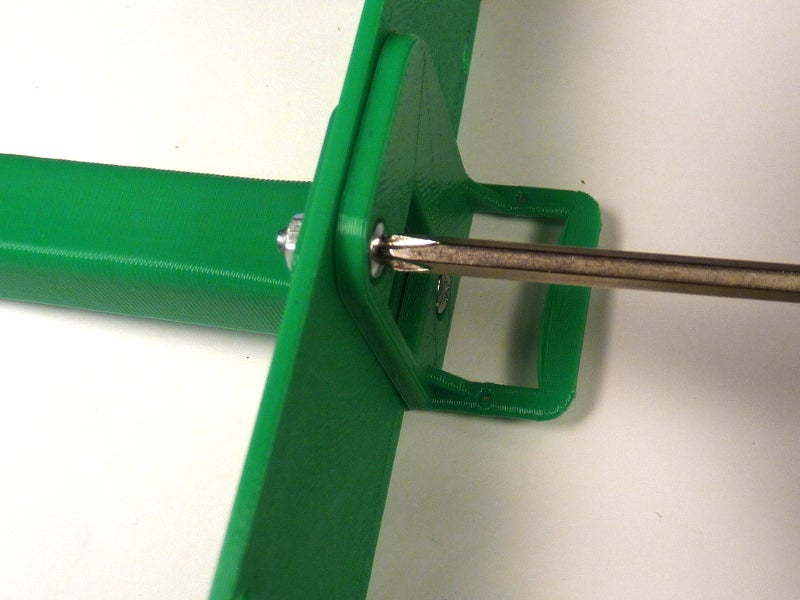
Step 5: Wheel Assembly
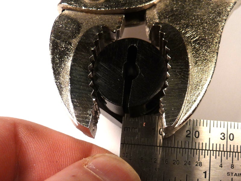
- Getting the hubs to grip the shaft is an issue since the shafts are 5 mm and the hub (which claims to be for 5 mm) is actually 6 mm. Using enough torque on the clamping screws is likely to strip them out, so I used a pair of vice-grips to close the tolerance first.
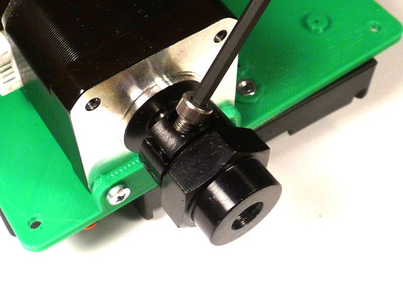
- After adjusting tolerance, slide hub on stepper shaft and tighten clamping screws.
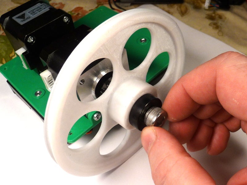
- Place the 3D wheel on the hub, insert large bolt, and tighten.
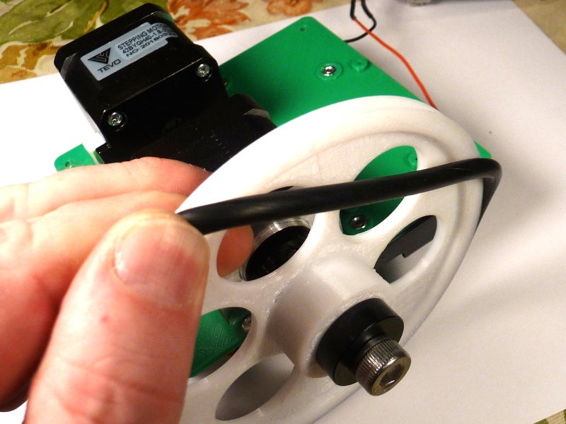
- Place O-ring over hub.
- Ensure that wheel rotates without wobble. Adjust if necessary.
Step 6: Wiring
Let us get the power out of the way so we can test the steppers. We need:
- The stepper shield requires between 8 and 35V to run the steppers.
- The steppers are rated for 3.4V, but are typically driven by 12V.
- The Bluno (Arduino) has a recommended input voltage of 7 - 12V, or can be powered directly by 5V USB.
The lithium battery cells have a nominal voltage of 3.7V. If we put three in series, that gives us 3 x 3.7V = 11.1 V and roughly 3 x 3000 mAh = 9000 mAh. The Bluno probably draws only 20 mA, so the majority of the drain will come from the steppers, which could draw up to an amp or more depending on load. That should give us hours of run time.
For testing, you can supply 12V regulated to the shield and 5V USB to the Arduino. It may be easier to just wire the batteries up to power both at the same time.
- Solder the battery holders in parallel as per the drawing.
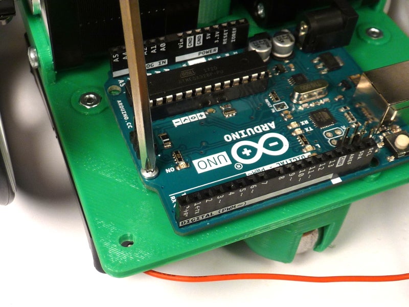
- Mount the Arduino using the #2 thread forming screws.
- Place the motor shield on top of the Arduino
- Strip the salvaged 2.1 mm x 5 mm jack wires and twist them together with the battery leads:
- White stripe is positive, twist with red battery lead.
- Insert the red lead in the VCC and black lead in GND on the motor shield.
Step 7: Stepping the Stepper
I had a little bit of trouble of piece together enough information to get this running, so hopefully this will help others. The key document you need is at https://www.dfrobot.com/wiki/index.php/Stepper_Motor_Shield_For_Arduino(DRV8825)_SKU:DRI0023
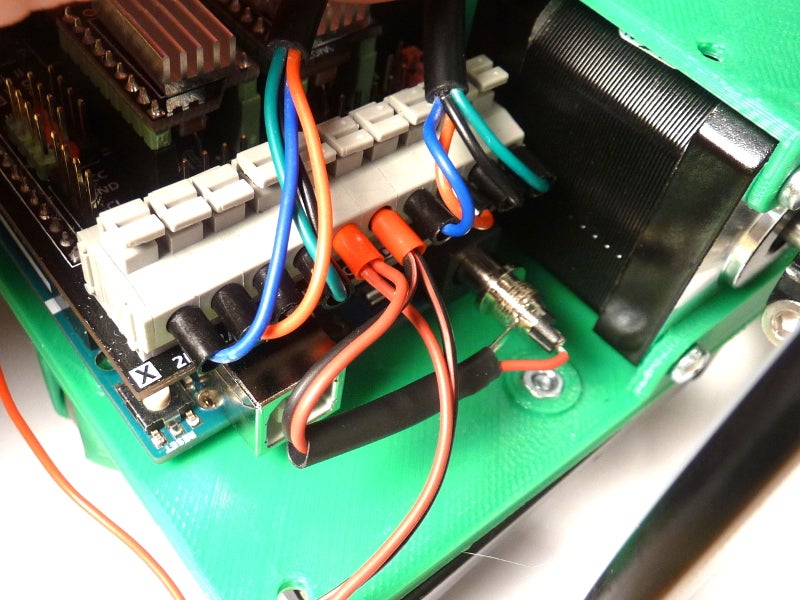
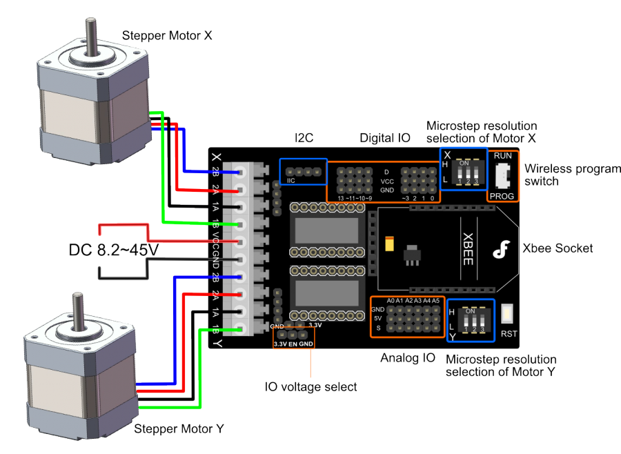
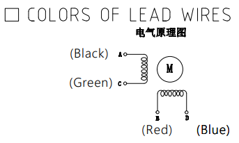
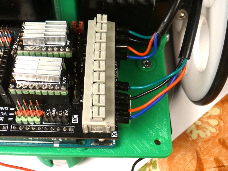
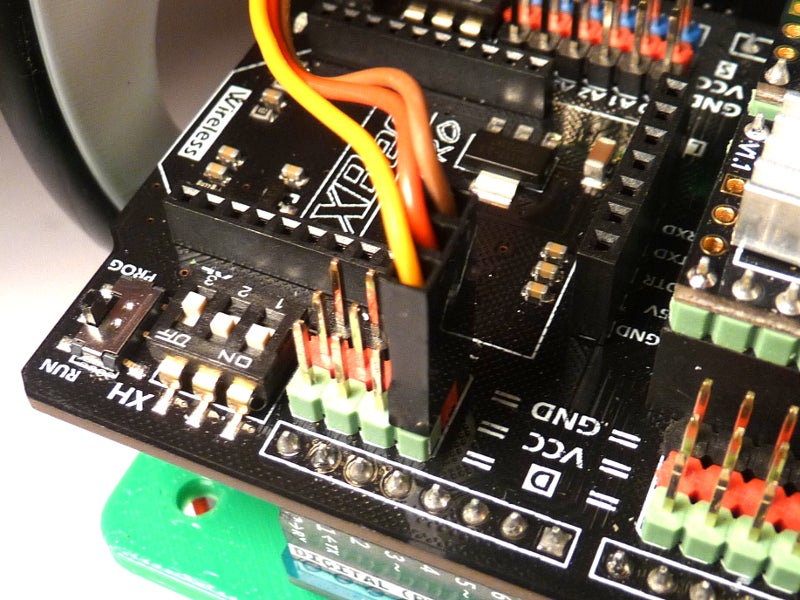
Connect the stepper wires and power supply to your shield:
- 2B Blue
- 2A Red
- 1A Black
- 1B Green
The provided example sketch worked for me, but is not too instructive. We will need to control speed and rotation as well as release the stepper motors when not in use to save power.
I found an modified an example from http://bildr.org/2011/06/easydriver/ which has helper functions. It only drives one stepper at a time, but will give you confidence we are on the right track. We will write some more sophisticated code later.
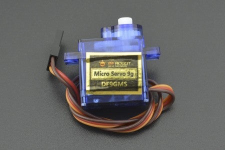
Step 8: Servo
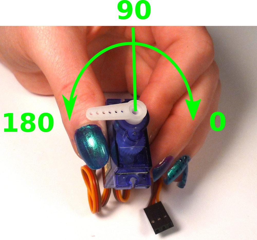
The servo is used to raise and lower the pen for drawing.
- Place the arm on the hub and gently rotate the stepper counter-clockwise looking down on it until it reaches the stop.
- Remove the arm and position it facing left (this will be the down position).
- Insert the small thread-forming screw and tighten.
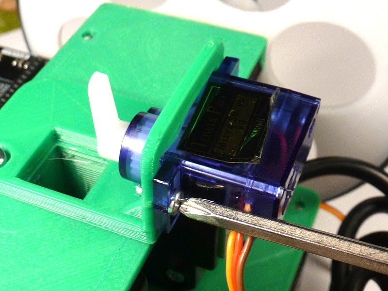
- Insert the servo in the mount with the hub end upward and attach using two larger thread-forming screws.
Step 9: Calibration
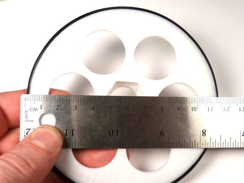
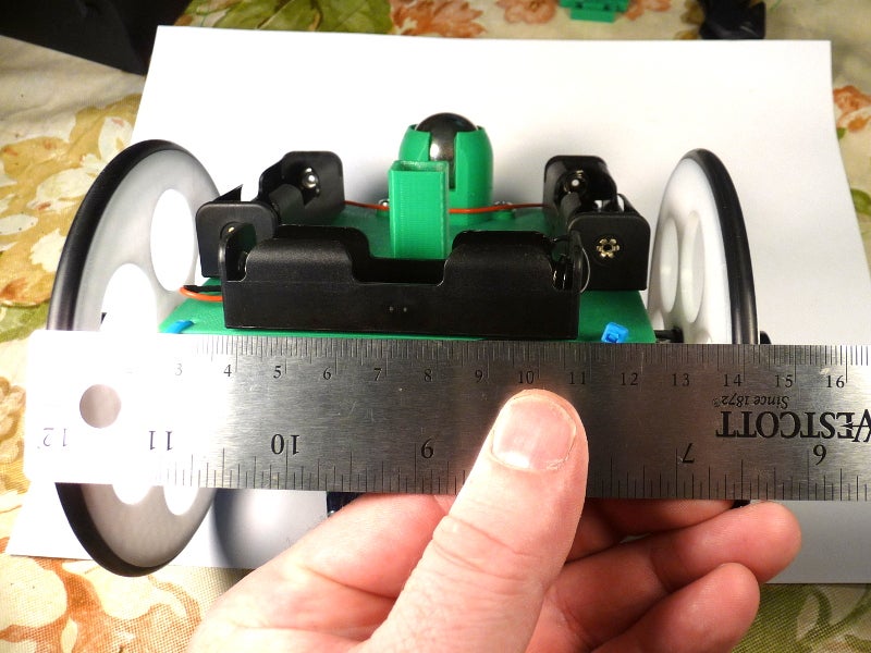
Because of variations in assembly and alignment, the robot must be calibrated so that it can move precised distances and angles.
- Measure the wheel diameter from the outer edges of the rubber o-ring.
- Measure the wheelbase from the center of the o-rings on the bottom of the robot (where it will contact the floor).
- Download attached calibration sketch
- Enter your measured parameters.
- Upload the sketch..
Prepare the pen:
- Remove the cap and slide the pen collar from the tip side.
- Insert pen in holder with servo arm straight up.
- Ensure pen does not touch paper in this position.I
- f the pen binds in the shaft, us a file to remove any roughness and increase the bore diameter.
Draw a square:
- Slide the power switch to "On".
- Wait several seconds for the bootloader to begin.
- After the robot completes it's first square, remove the pen and turn the robot off.

Adjust wheel_dia parameter first. Measure the length of side of the square. It should be 100 mm:
- If the measured distance is too long, increase wheel_dia.
- If the measured distance is too short, decrease wheel_dia.

After you have the distance calibration, adjust the wheel_base parameter which affects the angle of the turn. Place the robot on a fresh sheet of paper, turn it on and let it draw all four squares:
- If the robot is turning too sharply (box is rotating clockwise), decrease wheel_base value.
- If robot is not turning sharply enough (box is rotating counter-clockwise), increase wheel_base value.
- Because of rounding errors in the stepping code and slop in the gears of the inexpensive steppers, you will never get it perfect, so don't spend too much effort on it.
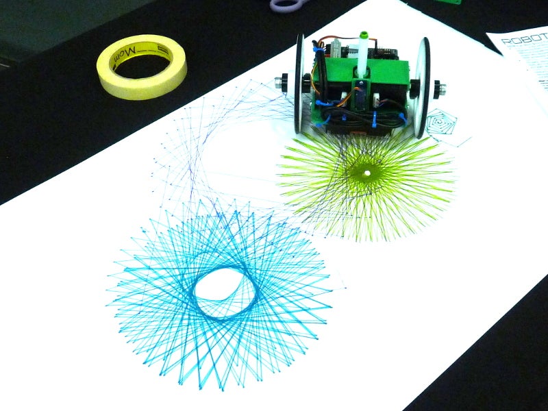
Step 10: Drawing
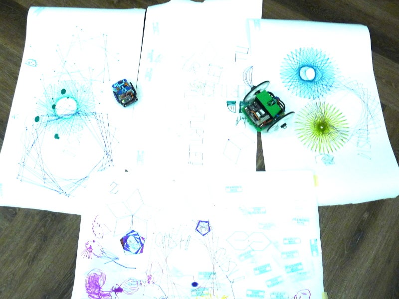
Time to do some drawing! Download the attached sketches to give you a start.
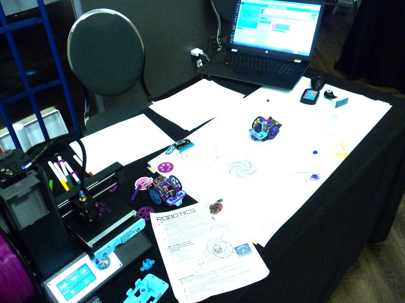
Step 11: Now What? Curriculum!
It works and draws nice squares. Now the fun begins.
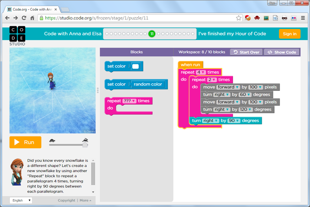
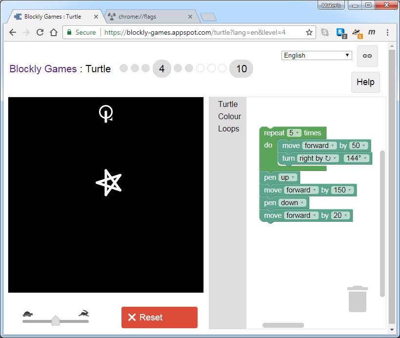
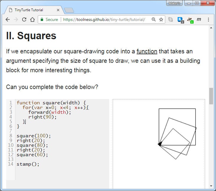
Here are a couple of resources for learning turtle graphics.
- https://blockly-games.appspot.com/ (block programming)
- TinyTurtle Tutorial (JavaScript)
- Code with Anna and Elsa from Hour of Code
I have also posted an Instructable about using the turtle robot these on-line resources with the Turtle Robot. In general, any Turtle JavaScript code can be pasted and run in the calibration sketch. You can test output online the a computer first and then uploaded it to your turtle to draw out in real life!
For students, here are a couple of project ideas:
- Program your robot to write your name!
- Design and 3D print a nameplate in TinkerCad from a template. It can be attached below your servo motor.
- Give your robot some personality with some hot glue and bling. (Just keep the wheels and eyes clear of obstructions).
- From the OSTR_eyes sketch, design and test an algorithm to navigate a room. What do you do when one eye detects something. Both eyes? Could you incorporate Arduino's random() function.
- Construct a maze on a large sheet of paper on the floor and program your robot to navigate through it.
- Construct a maze with walls and design an algorithm to navigate it automatically.
- The button in between the LEDs hasn't been put to use yet, and is connected to Arduino pin "A3". What could it be used for? Use it to turn an LED on and off to start with.
- If you didn't do the Investigation section of the "Firmware (FW): Testing and Blinking" step, go back and give it a try.
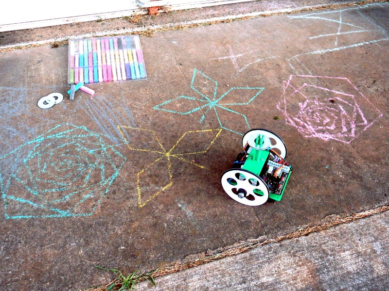
Step 12: But Wait, There Is More!
If you've been paying attention, you noticed the barrel is square. By some strange cosmic coincidence, pastel artist chalk is the same width as the diameter of the Crayola markers. All we need is a way to put enough pressure on the chalk, and we are a sidewalk artist.
You will need:
- 3D printed barrel and ram (https://www.thingiverse.com/thing:2976527)
- Chalk, either the pastel square artist chalk or small round chalk (not the fat sidewalk stuff).
- 3/4" washers for weight.
Steps:
- Print out the two attached files.- Remove the servo and servo holder.- Attach the square feed barrel.- Sharpen the chalk to a near point.- Place chalk in barrel.- Place ram in barrel.- Place washer weight on ram.
This article was first published on Instructables,
cr: https://www.instructables.com/DFRobot-Turtle-Robot/
Author: MakersBox


