Read Duty Cycle of a PWM Signal Using Visuino

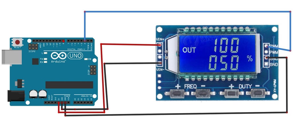
In this tutorial we are going to read the Duty Cycle of a PWM signal using Visuino. For a PWM source we are going to use a PWM generator connected to the Arduino interrupt digital pin [2],

We are going to measure the pulse width of the HIGH and LOW then use this formula

TotalDuration = highDuration + lowDuration;

DutyCycle = 100.0 * highDuration / totalDuration

to get the Duty Cycle in percentage.

Watch the video!

STEP 1
What You Will Need


What You Will Need

What You Will Need

What You Will Need

What You Will Need

Arduino UNO or Arduino Mega (or any other board)Some PWM signal source like  XY-LPWMVisuino program: Download VisuinoJumper wires
STEP 2
The Circuit

The Circuit

The Circuit

Connect Arduino pin [5V] to the PWM Module pin [VIN+]Connect Arduino pin [GND] to the PWM Module pin [VIN-]Connect PWM Module pin [PWM] to Arduino digital pin [2]Connect PWM Module pin [GND] to Arduino pin [GND]
STEP 3
Start Visuino, and Select the Arduino UNO Board Type

Start Visuino, and Select the Arduino UNO Board Type

Start Visuino, and Select the Arduino UNO Board Type

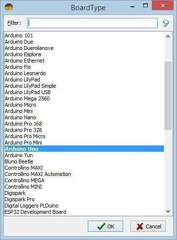
Start Visuino as shown in the first picture Click on the "Tools" button on the Arduino component (Picture 1) in Visuino When the dialog appears, select "Arduino UNO" as shown on Picture 2

STEP 4
In Visuino Add & Set Components

In Visuino Add & Set Components

In Visuino Add & Set Components

In Visuino Add & Set Components

In Visuino Add & Set Components

In Visuino Add & Set Components

In Visuino Add & Set Components

In Visuino Add & Set Components

In Visuino Add & Set Components

In Visuino Add & Set Components

In Visuino Add & Set Components

Add "Digital Multi Source" componentAdd "Digital (Boolean) Inverter (Not)" componentAdd 2X "Pulse Meter(Measure Period)" componentAdd "Unsigned To Analog" componentAdd "Analog Multi Source" componentAdd "Add Analog" componentAdd "Divide Analog By Value" componentAdd "Multiply Analog By Value" component


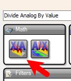
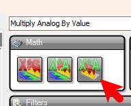
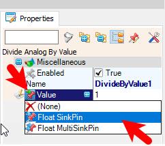
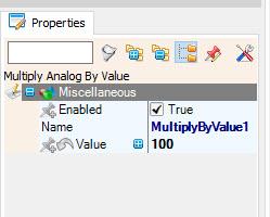
Select "DivideByValue1" and in the properties window select "Value" and click on the pin icon and select "Float SinkPin"Select "MultiplyByValue1" and in the properties window set "Value" to 100
STEP 5
In Visuino Connect Components
Connect Arduino digital pin [2] to "MultiSource1" pin [In]Connect "MultiSource1" pin [0] to "PulseMeter1" pin [In]Connect "MultiSource1" pin [1] to "Inverter1" pin [In]Connect "Inverter1" pin [Out] to "PulseMeter2" pin [In]Connect "PulseMeter1" pin [Out] to "UnsignedToAnalog1" pin [In]Connect "PulseMeter2" pin [Out] to "UnsignedToAnalog2" pin [In]Connect "UnsignedToAnalog1" pin [Out] to "MultiSource2" pin [In]Connect "MultiSource2" pin [0] to "Add1" pin [0]Connect "MultiSource2" pin [1] to "DivideByValue1" pin [In]Connect "UnsignedToAnalog2" pin [Out] to "Add1" pin [1]Connect "Add1" pin [Out] to "DivideByValue1" pin [Value]Connect "DivideByValue1" pin [Out] to "MultiplyByValue1" pin [In]Connect "MultiplyByValue1" pin [Out] to Arduino Serial pin [In]
STEP 6
Duty Cycle Formula Explained

We are going to measure the pulse width of the HIGH and LOW then use this formula

TotalDuration = highDuration + lowDuration;

DutyCycle = 100.0 * highDuration / totalDuration

to get the Duty Cycle in percentage.


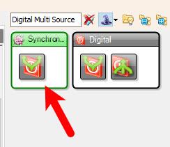
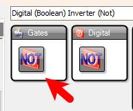
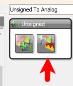
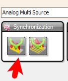
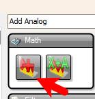
On the schematic you can see that we split the digital pulses using "MultiSource1", First signal we take it directly to "PulseMeter1" to get the pulse period when it is HIGH, Second signal we invert it using "Inverter1" and we take it to "PulseMeter2" to get a pulse period when its LOW, we convert both periods to analog values and we sum them to get the total length using "Add1", then we use "DivideByValue1" to divide HIGH pulse period / Sum of both periods, and we multiply all at the end by 100 using "MultiplyByValue1"

STEP 7
Generate, Compile, and Upload the Arduino Code

Generate, Compile, and Upload the Arduino Code

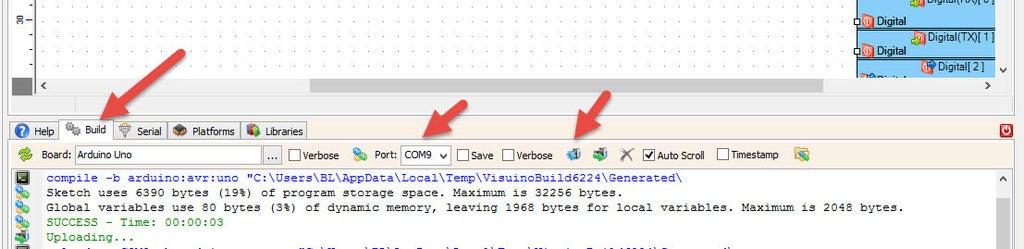
In Visuino, at the bottom click on the "Build" Tab, make sure the correct port is selected, then click on the "Compile/Build and Upload" button.

STEP 8
Play

Play

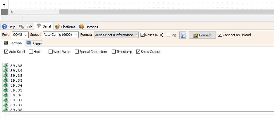
If you power the Arduino module and click connect in the "Serial" tab, you will be able to see the Duty Cycle of the Input PWM signal.

Congratulations! You have completed your project with Visuino. Also attached is the Visuino project, that I created for this tutorial, you can download it and open it in Visuino: https://www.visuino.com

icon pwm-read.zip 1KB Download(0)
License
All Rights
Reserved
licensBg
0