
This tutorial shows how to use the DS1307 Real-Time Clock (RTC) with a GC9A01 Display in Visuino to keep and display accurate time. The project reads the current time from the DS1307 module and creates an analog clock on the GC9A01 circular display.
Watch the video!
Step 1: What You Will Need


Note: If you plan to use a lot of graphics on the display or more sensore/modules then you might need a board with larger memory like Arduino UNO R4 WiFi
Step 2: The Circuit

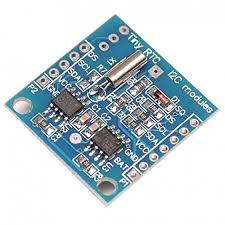
Connect RTC DS1307 module pin[VCC] to Arduino pin[5V]Connect RTC DS1307 module pin[GND] to Arduino pin[GND]Connect RTC DS1307 module pin[SDA] to Arduino pin[SDA]Connect RTC DS1307 module pin[SCL] to Arduino pin[SCL]
Step 3: Start Visuino, and Select the Arduino UNO Board Type

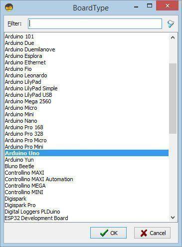
Start Visuino as shown in the first picture Click on the "Tools" button on the Arduino component (Picture 1) in Visuino When the dialog appears, select "Arduino UNO" as shown on Picture 2
Step 4: In Visuino Add & Set Components
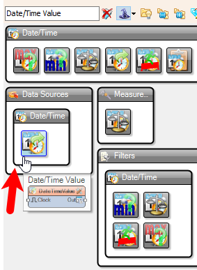


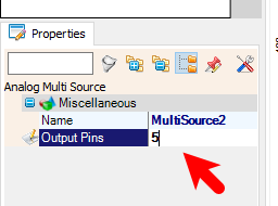
Select "DateTimeValue1" and in the properties window set under "Value" current time & dateFor All Analog Multi Source components in the properties window set "Output Pins" to 5
Step 5: In Visuino Set the Display
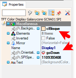


Select "Display1" and in the properties window set "Background Color" to clBisque and "Orientation" to goDown
Step 1: Open the Display Configuration
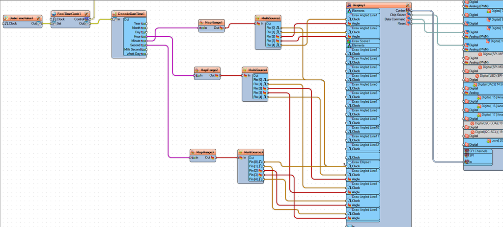
Double-click on the Display1 component in the diagram.This will open the Elements window for the display.Drag 6X "Draw Angled Line" element to the left sideDrag "Draw Scene" to the left sideDrag "Draw Ellipse" to the left sideStep 2: Configure Graphical Elements
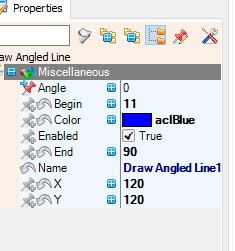
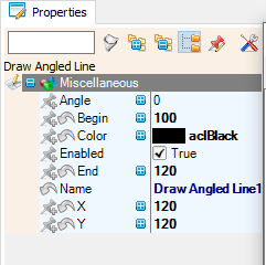
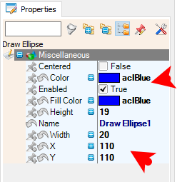
Draw Angled Line1:In the Elements window, locate the Draw Angled Line1 element.In the Properties window, configure the following:Set Begin to 11.Set End to 90.Set X to 120.Set Y to 120.Set Color to aclBlueSelect Angle and click on the pin icon and select Float SinkPinDraw Angled Line2:In the Elements window, locate the Draw Angled Line2 element.In the Properties window, configure the following:Set Begin to 11.Set End to 90.Set X to 120.Set Y to 120.Set Color to aclBisqueSelect Angle and click on the pin icon and select Float SinkPinDraw Angled Line3:In the Elements window, locate the Draw Angled Line3 element.In the Properties window, configure the following:Set Begin to 11.Set End to 80.Set X to 120.Set Y to 120.Set Color to aclBlueSelect "Angle" and click on the pin icon and select "Float SinkPin"Draw Angled Line4:In the Elements window, locate the Draw Angled Line4 element.In the Properties window, configure the following:Set Begin to 11.Set End to 80.Set X to 120.Set Y to 120.Set Color to aclBisqueSelect "Angle" and click on the pin icon and select "Float SinkPin"Draw Angled Line5:In the Elements window, locate the Draw Angled Line5 element.In the Properties window, configure the following:Set Begin to 11.Set End to 100.Set X to 120.Set Y to 120.Set Color to aclRedSelect "Angle" and click on the pin icon and select "Float SinkPin"Draw Angled Line6:In the Elements window, locate the Draw Angled Line6 element.In the Properties window, configure the following:Set Begin to 11.Set End to 100.Set X to 120.Set Y to 120.Set Color to aclBisqueSelect Angle and click on the pin icon and select Float SinkPinDraw Scene1:In the Elements window, locate the Draw Scene1 element.In the Properties window, select Elements and click on the 3 dots button.In the Elements window, add 12X Draw Angled Line elements.For each Draw Angled Line element, set the properties as follows:Draw Angled Line1:Name: Draw Angled Line1Properties:Begin: 100Angle: 0X: 120Color: aclBlackEnd: 120Y: 120Draw Angled Line2:Name: Draw Angled Line2Properties:Begin: 100Angle: 30X: 120Color: aclBlackEnd: 120Y: 120Draw Angled Line3:Name: Draw Angled Line3Properties:Begin: 100Angle: 60X: 120Color: aclBlackEnd: 120Y: 120Draw Angled Line4:Name: Draw Angled Line4Properties:Begin: 100Angle: 90X: 120Color: aclBlackEnd: 120Y: 120Draw Angled Line5:Name: Draw Angled Line5Properties:Begin: 100Angle: 120X: 120Color: aclBlackEnd: 120Y: 120Draw Angled Line6:Name: Draw Angled Line6Properties:Begin: 100Angle: 150X: 120Color: aclBlackEnd: 120Y: 120Draw Angled Line7:Name: Draw Angled Line7Properties:Begin: 100Angle: 180X: 120Color: aclBlackEnd: 120Y: 120Draw Angled Line8:Name: Draw Angled Line8Properties:Begin: 100Angle: 210X: 120Color: aclBlackEnd: 120Y: 120Draw Angled Line9:Name: Draw Angled Line9Properties:Begin: 100Angle: 240X: 120Color: aclBlackEnd: 120Y: 120Draw Angled Line10:Name: Draw Angled Line10Properties:Begin: 100Angle: 270X: 120Color: aclBlackEnd: 120Y: 120Draw Angled Line11:Name: Draw Angled Line11Properties:Begin: 100Angle: 300X: 120Color: aclBlackEnd: 120Y: 120Draw Angled Line12:Name: Draw Angled Line12Properties:Begin: 100Angle: 330X: 120Color: aclBlackEnd: 120Y: 120Close the Elements window.Draw Ellipse1:In the Elements window, locate the Draw Ellipse1 element.In the Properties window, configure the following:Set Width to 20.Set Height to 19.Set X to 110.Set Y to 110.Set FillColor to aclBlueSet Color to aclBlueStep 3: Connect Clock Inputs
Draw Ellipse1:Connect the ClockInputPin to MultiSource2 pin [Pin 0], MultiSource1 pin [Pin 0], and MultiSource3 pin [Pin 0].Draw Angled Line1:Connect the ClockInputPin to MultiSource2 pin [Pin 4].Draw Angled Line2:Connect the ClockInputPin to MultiSource2 pin [Pin 1].Draw Angled Line3:Connect the ClockInputPin to MultiSource1 pin [Pin 4].Draw Angled Line4:Connect the ClockInputPin to MultiSource1 pin [Pin 1].Draw Angled Line5:Connect the ClockInputPin to MultiSource3 pin [Pin 4].Draw Angled Line6:Connect the ClockInputPin to MultiSource3 pin [Pin 1].
Step 6: In Visuino Connect Components
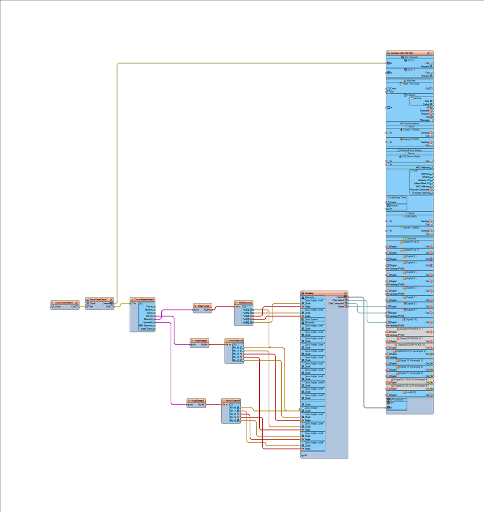
Connect "Display1" pin [Chip Select] to Arduino digital pin [10]Connect "Display1" pin [Data Command] to Arduino digital pin [9]Connect "Display1" pin [Reset] to Arduino digital pin [8]Connect "Display1" Control pin [SPI] to Arduino SPI pin [In]
Step 7: Generate, Compile, and Upload the Arduino Code
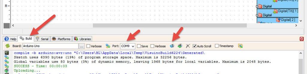
In Visuino, at the bottom click on the "Build" Tab, make sure the correct port is selected, then click on the "Compile/Build and Upload" button.
Step 8: Play
Congratulations! You have completed your project with Visuino. Also attached is the Visuino project, that I created for this Project, you can download it here and open it in Visuino: https://www.visuino.eu


