
In this tutorial we will make a colorful Volume Indicator using GC9A01 SPI Display, rotary encoder, Arduino and Visuino program.
Watch the video!
Step 1: What You Will Need

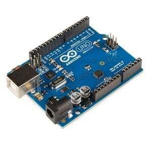


Note: If you plan to use a lot of graphics on the display or more sensore/modules then you might need a board with larger memory like Arduino UNO R4 WiFi
Step 2: The Circuit

Step 3: Start Visuino, and Select the Arduino UNO Board Type

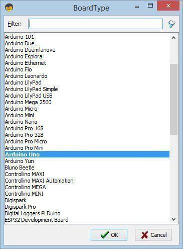
Start Visuino as shown in the first picture Click on the "Tools" button on the Arduino component (Picture 1) in Visuino When the dialog appears, select "Arduino UNO" as shown on Picture 2
Step 4: In Visuino Add Components
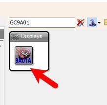
Step 5: In Visuino Set the Display


Step 1: Open the Display Configuration
Double-click on the "Display1"component in the diagram.This will open the Elements window for the display.Step 2: Add a Draw Scene
In the Elements window, locate the Draw Scene element.Drag the Draw Scene element to the left side of the window.In the Properties window, select the Elements property.Click on the 3 dots button next to the Elements property to open the Elements Editor.Step 3: Add Draw Polygon Elements
In the Elements Editor, locate the Draw Polygon element.Drag8X Draw Polygon element to the left side of the window.In the Properties window, configure the following:Set the Color property to aclBlack.Select the Fill Color property and click on the pin icon.From the dropdown, select Alpha Color SinkPin.Set the X property to 120.Set the Y property to 120.Step 4: Configure Polygon Points
In the Properties window, locate the Points property.Click on the 3 dots button next to the Points property to open the Points Editor.In the Points Editor, follow these steps for each polygon:Polygon 1:
Drag a Point element to the left side.In the Properties window, set:X to 0Y to 0Drag another Point element to the left side.In the Properties window, set:X to 0Y to -130Drag another Point element to the left side.In the Properties window, set:X to 120Y to -130Drag another Point element to the left side.In the Properties window, set:X to 120Y to 0Close the Points Window.Polygon 2:
Repeat the process for Polygon 2:Point 1: X = 0, Y = 0Point 2: X = 120, Y = -130Point 3: X = 130, Y = 0Point 4: X = 0, Y = 0Close the Points Window.Polygon 3:
Repeat the process for Polygon 3:Point 1: X = 0, Y = 0Point 2: X = 120, Y = 0Point 3: X = 120, Y = 130Point 4: X = 0, Y = 0Close the Points Window.Polygon 4:
Repeat the process for Polygon 4:Point 1: X = 0, Y = 0Point 2: X = 0, Y = 130Point 3: X = 120, Y = 130Point 4: X = 120, Y = 0Close the Points Window.Polygon 5:
Repeat the process for Polygon 5:Point 1: X = 0, Y = 0Point 2: X = 0, Y = 130Point 3: X = -120, Y = 130Point 4: X = 0, Y = 0Close the Points Window.Polygon 6:
Repeat the process for Polygon 6:Point 1: X = 0, Y = 0Point 2: X = -120, Y = 0Point 3: X = -120, Y = 130Point 4: X = 0, Y = 0Close the Points Window.Polygon 7:
Repeat the process for Polygon 7:Point 1: X = 0, Y = 0Point 2: X = -120, Y = 0Point 3: X = -120, Y = -130Point 4: X = 0, Y = 0Close the Points Window.Polygon 8:
Repeat the process for Polygon 8:Point 1: X = 0, Y = 0Point 2: X = 0, Y = -130Point 3: X = -120, Y = -130Point 4: X = 0, Y = 0Close the Points Window.Close all the windows.
Step 6: In Visuino Set Components
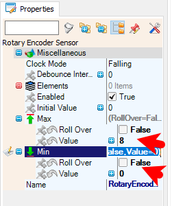

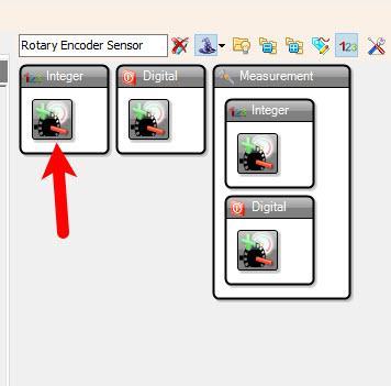
Select "RotaryEncoderSensor1" and in the properties window set
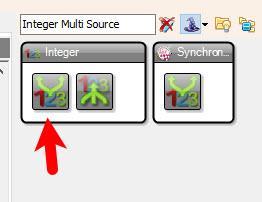
"Max" > "Value" to 8 and "Max" > "Roll Over" to False"Min" > "Value" to 0 and "Min" > "Roll Over" to FalseSelect "MultiSource1" and in the properties window set "Output pins" to 9
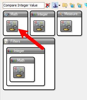
Step-by-Step Tutorial for Compare Components
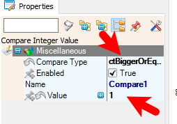
Compare1
Select Compare1 in the diagram.In the Properties window:Set Compare Type to ctBiggerOrEqual.Set Value to 1.Compare2
Select Compare2 in the diagram.In the Properties window:Set Compare Type to ctBiggerOrEqual.Set Value to 2.Compare3
Select Compare3 in the diagram.In the Properties window:Set Compare Type to ctBiggerOrEqual.Set Value to 3.Compare4
Select Compare4 in the diagram.In the Properties window:Set Compare Type to ctBiggerOrEqual.Set Value to 4.Compare5
Select Compare5 in the diagram.In the Properties window:Set Compare Type to ctBiggerOrEqual.Set Value to 5.Compare6
Select Compare6 in the diagram.In the Properties window:Set Compare Type to ctBiggerOrEqual.Set Value to 6.Compare7
Select Compare7 in the diagram.In the Properties window:Set Compare Type to ctBiggerOrEqual.Set Value to 7.Compare8
Select Compare8 in the diagram.In the Properties window:Set Compare Type to ctBiggerOrEqual.Set Value to 8.Summary of Compare Components
Each Compare component is configured to check if the input value (from the rotary encoder) is greater than or equal to a specific threshold (1 to 8).The output of each Compare component is connected to a DigitalToColor component, which maps the result to a specific color for the corresponding polygon on the display.
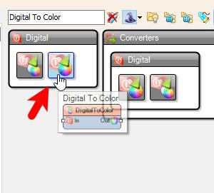
Step-by-Step Tutorial for DigitalToColor Components
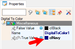
DigitalToColor1
Select DigitalToColor1 in the diagram.In the Properties window:Set TrueValue to clNavyDigitalToColor2
Select DigitalToColor2 in the diagram.In the Properties window:Set TrueValue to clNavyDigitalToColor3
Select DigitalToColor3 in the diagram.In the Properties window:Set TrueValue to clBlueDigitalToColor4
Select DigitalToColor4 in the diagram.In the Properties window:Set TrueValue to clBlueDigitalToColor5
Select DigitalToColor5 in the diagram.In the Properties window:Set TrueValue to clGreenDigitalToColor6
Select DigitalToColor6 in the diagram.In the Properties window:Set TrueValue to clMaroonDigitalToColor7
Select DigitalToColor7 in the diagram.In the Properties window:Set TrueValue to clMaroonDigitalToColor8
Select DigitalToColor8 in the diagram.In the Properties window:Set TrueValue to clRedSummary of DigitalToColor Components
Each DigitalToColor component maps the output of a Compare component to a specific color.The TrueValue property defines the color that will be applied to the corresponding polygon when the condition is met.Note: you can freely experiment with other colors
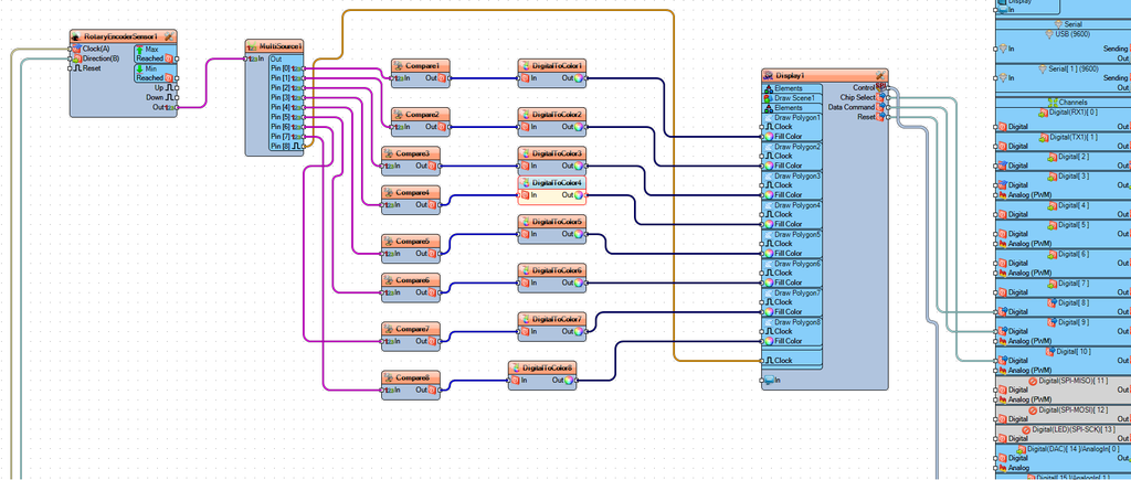
How It Works
The RotaryEncoderSensor1 sends its value to MultiSource1, which distributes the value to all Compare components.Each Compare component checks if the encoder's value meets its condition (e.g., ctBiggerOrEqual with a specific value).If the condition is met, the Compare component outputs a signal to the corresponding DigitalToColor component.The DigitalToColor component sets the Fill Color of the associated polygon on the display.
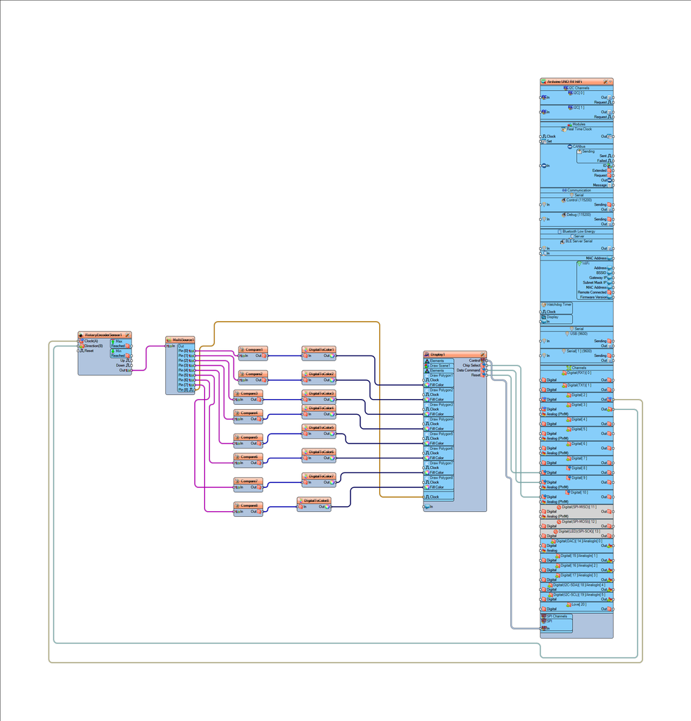
Step 7: In Visuino Connect Components
RotaryEncoderSensor1
Connect RotaryEncoderSensor1 pin [Out] to MultiSource1 pin [In].MultiSource1
Connect MultiSource1 pin [Pin 0] to Compare1 pin [In].Connect MultiSource1 pin [Pin 1] to Compare2 pin [In].Connect MultiSource1 pin [Pin 2] to Compare3 pin [In].Connect MultiSource1 pin [Pin 3] to Compare4 pin [In].Connect MultiSource1 pin [Pin 4] to Compare5 pin [In].Connect MultiSource1 pin [Pin 5] to Compare6 pin [In].Connect MultiSource1 pin [Pin 6] to Compare7 pin [In].Connect MultiSource1 pin [Pin 7] to Compare8 pin [In].Connect MultiSource1 pin [Pin 8] to Display1.Elements.Draw Scene1 pin [Clock].Compare1
Connect Compare1 pin [Out] to DigitalToColor1 pin [In].Compare2
Connect Compare2 pin [Out] to DigitalToColor2 pin [In].Compare3
Connect Compare3 pin [Out] to DigitalToColor3 pin [In].Compare4
Connect Compare4 pin [Out] to DigitalToColor4 pin [In].Compare5
Connect Compare5 pin [Out] to DigitalToColor5 pin [In].Compare6
Connect Compare6 pin [Out] to DigitalToColor6 pin [In].Compare7
Connect Compare7 pin [Out] to DigitalToColor7 pin [In].Compare8
Connect Compare8 pin [Out] to DigitalToColor8 pin [In].DigitalToColor1
Connect DigitalToColor1 pin [Out] to Display1.Elements.Draw Polygon1 pin [FillColor].DigitalToColor2
Connect DigitalToColor2 pin [Out] to Display1.Elements.Draw Polygon2 pin [FillColor].DigitalToColor3
Connect DigitalToColor3 pin [Out] to Display1.Elements.Draw Polygon3 pin [FillColor].DigitalToColor4
Connect DigitalToColor4 pin [Out] to Display1.Elements.Draw Polygon4 pin [FillColor].DigitalToColor5
Connect DigitalToColor5 pin [Out] to Display1.Elements.Draw Polygon5 pin [FillColor].DigitalToColor6
Connect DigitalToColor6 pin [Out] to Display1.Elements.Draw Polygon6 pin [FillColor].DigitalToColor7
Connect DigitalToColor7 pin [Out] to Display1.Elements.Draw Polygon7 pin [FillColor].DigitalToColor8
Connect DigitalToColor8 pin [Out] to Display1.Elements.Draw Polygon8 pin [FillColor].Display1
Connect Display1 pin [ChipSelect] to Arduino Digital pin[10]Connect Display1 pin [ResetOutputPin] to Arduino Digital pin[8]Connect Display1 pin [DataCommandOutputPin] to Arduino digital[9]Connect Display1 pin [Control] to Arduino SPI pin [In]Arduino
Connect Arduino Digital pin [2] pin to RotaryEncoderSensor1 pin [Clock].Connect Arduino Digital pin [3] pin to RotaryEncoderSensor1 pin [Direction].
Step 8: Generate, Compile, and Upload the Arduino Code
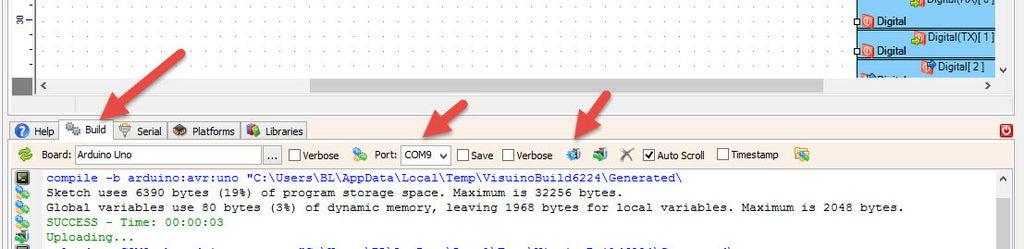
In Visuino, at the bottom click on the "Build" Tab, make sure the correct port is selected, then click on the "Compile/Build and Upload" button.
Step 9: Play
Congratulations! You have completed your project with Visuino. Also attached is the Visuino project, that I created for this tutorial, you can download it and open it in Visuino: https://www.visuino.eu


