
Learn how to use the INA219 DC Current Sensor with Visuino and Arduino to measure and display current in real time! This project shows you how to connect the sensor and display the measured current on an OLED display. Perfect for monitoring power consumption in your circuits!
Watch the Video!
Step 1: What You Will Need


Step 2: The Circuit
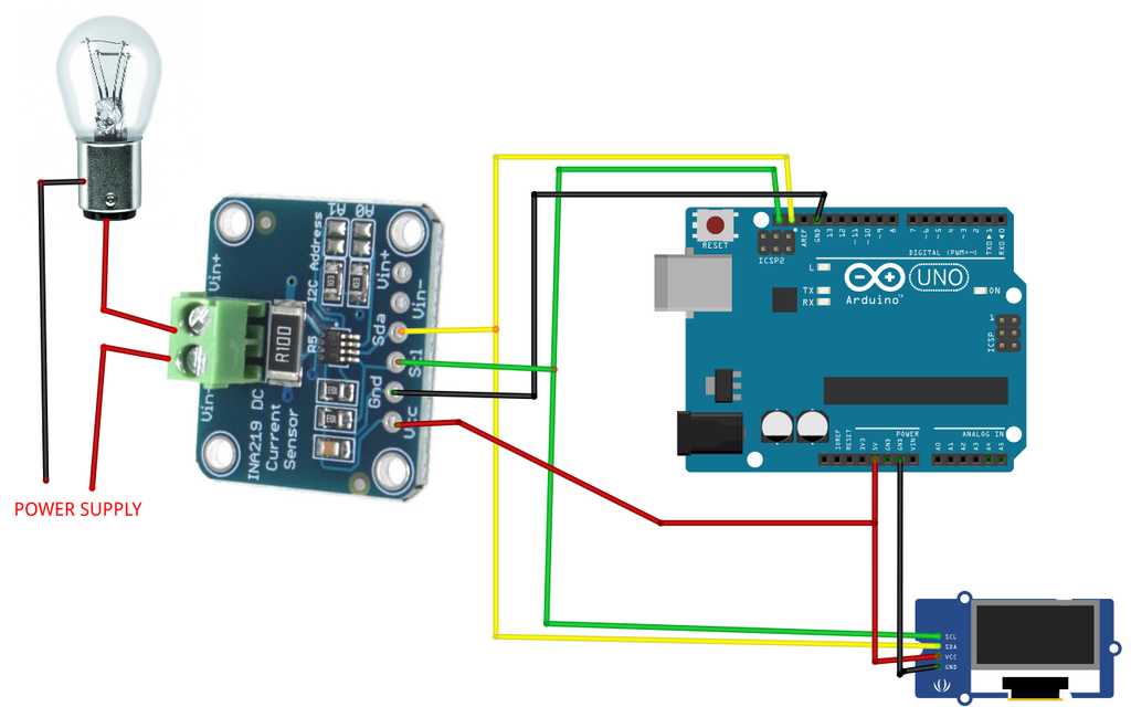
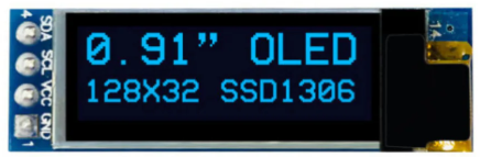
Connect OLED Display pin [SCL] to Arduino pin [SCL]Connect OLED Display pin [SDA] to Arduino pin [SDA]Connect OLED Display pin [VCC] to Arduino pin [5v]Connect OLED Display pin [GND] to Arduino pin [GND]
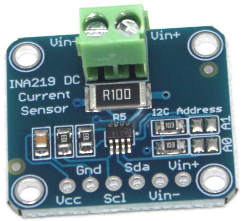
Connect Power Supply (+) to INA219 pin [Vin -]Connect Light Bulb (+) to INA219 pin [Vin +]Connect Light Bulb (-) to Connect Power Supply (-)
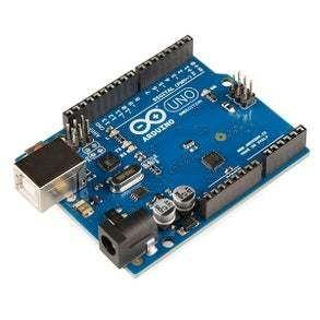
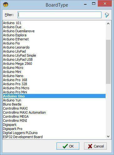
Step 3: Start Visuino, and Select the Arduino UNO Board Type

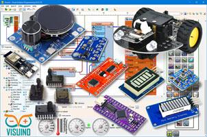
The Visuino: https://www.visuino.com also needs to be installed. Download Free version or register for a Free Trial.
Start Visuino as shown in the first picture Click on the "Tools" button on the Arduino component (Picture 1) in Visuino When the dialog appears, select "Arduino UNO" as shown on Picture 2
Step 4: In Visuino Add, Set & Connect Components
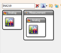
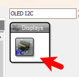


Add "INA219" componentAdd "OLED I2C" component
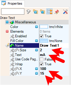
Double click on the "DisplayOLED1" component and in the Elements window drag "Text Field" to the left side and in the properties window set "Size" to 2, "Width" to 10 and "Y" to 15in the Elements window drag "Draw Text" to the left side and in the properties window set "Size" to 2, "Text" to mA, "X" to 100 and "Y" to 15Close the Elements window
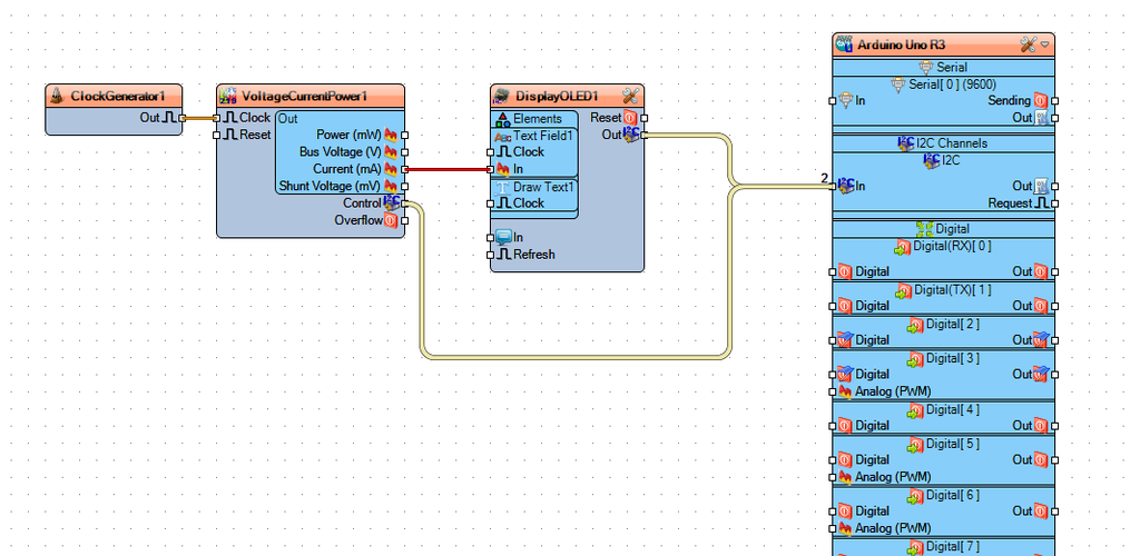
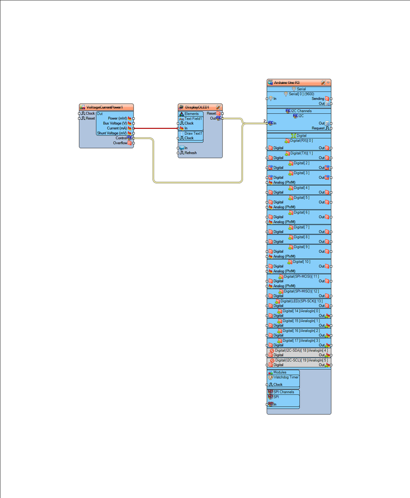
Connect "VoltageCurrentPower1" pin [Current mA] to "DisplayOLED1" > "Text Field1" pin [In]Connect "VoltageCurrentPower1" Control pin [I2C] to Arduino pin [I2C]Connect "DisplayOLED1" pin [I2C] to Arduino pin [I2C]
Step 5: Generate, Compile, and Upload the Arduino Code
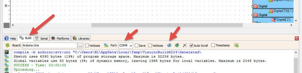
In Visuino, at the bottom click on the "Build" Tab, make sure the correct port is selected, then click on the "Compile/Build and Upload" button.
Step 6: Play
Congratulations! You have completed your project with Visuino. Also attached is the Visuino project, that I created for this Instructable, you can download it and open it in Visuino: https://www.visuino.com


