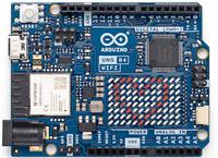
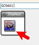
In this tutorial we will make a Gear Shift Indicator using GC9A01 SPI Display, Arduino and Visuino program.
Watch the Video!


Note: the board should have enough memory, that is why I choose to use Arduino R4, if you want to use a board with less memory such as Arduino R3 then skip the part where lines change color, you will find the Visuino files at the bottom including project that requires less memory.
GC9A01 SPI DisplayRotary Encoder (optional)Jumper wiresBreadboardVisuino program: Download Visuino

Connecting Encoder module:
Connect Encoder module pin [CLK] to Arduino digital pin [2]Connect Encoder module pin [DT] to Arduino digital pin [3]Connect Encoder module pin [SW] to Arduino digital pin [4]
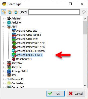
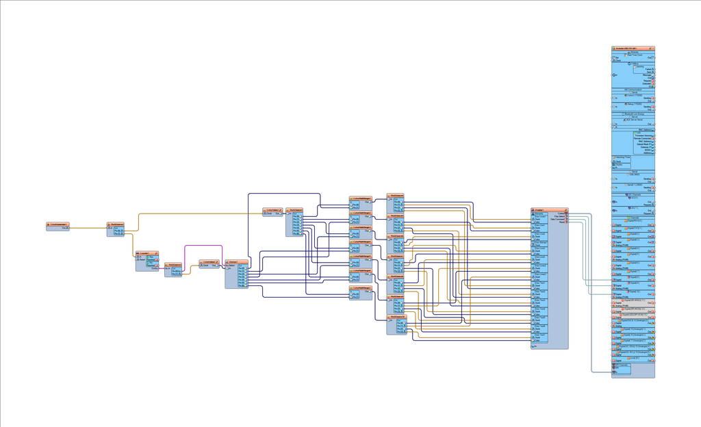
Start Visuino as shown in the first picture Click on the "Tools" button on the Arduino component (Picture 1) in Visuino When the dialog appears, select "Arduino UNO R4 WiFi" as shown on Picture 2


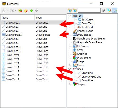


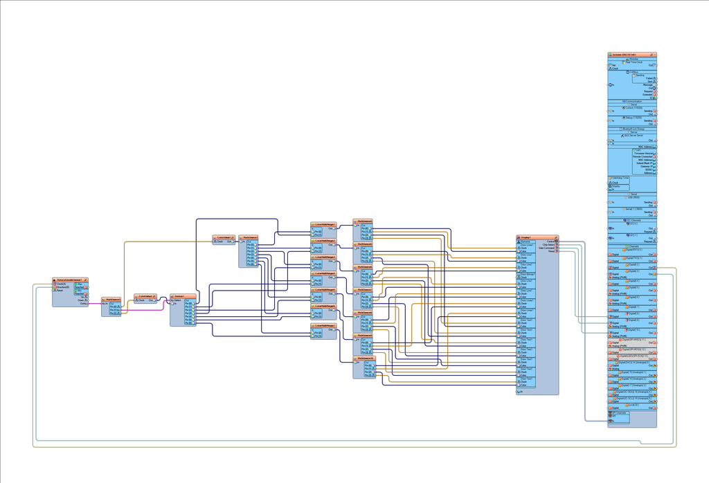
Double click on the "Display1" and in the Elements window Drag to the left side:
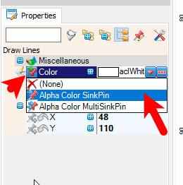
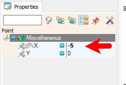
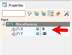
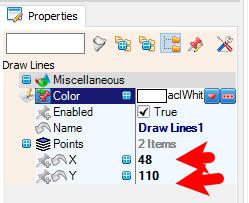
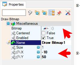
3X "Draw Lines""Draw Bitmap"4X "Draw Line"7X "Draw Text"Select "Draw Lines1" and in the properties window select "Color" and click on the pin icon and select "Alpha Color SinkPin", set "X" to 84 and "Y" to 110, Select "Points" and click on the 3 dots butoon and in the "Points" window drag "Point" to the left side and in the properties window set "X" to -5, drag another "Point" to the left side and in the properties window set "X" to -5 and "Y" to -30, Close the "Points" windowSelect "Draw Lines2" and in the properties window select "Color" and click on the pin icon and select "Alpha Color SinkPin", set "X" to 175 and "Y" to 110, Select "Points" and click on the 3 dots butoon and in the "Points" window drag "Point" to the left side and in the properties window set "X" to 10, drag another "Point" to the left side and in the properties window set "X" to 10 and "Y" to -30, Close the "Points" window Select "Draw Lines3" and in the properties window select "Color" and click on the pin icon and select "Alpha Color SinkPin", set "X" to 175 and "Y" to 110, Select "Points" and click on the 3 dots butoon and in the "Points" window drag "Point" to the left side and in the properties window set "X" to 10, drag another "Point" to the left side and in the properties window set "X" to 10 and "Y" to 40, Close the "Points" windowSelect "Draw Line1" and in the properties window select "Color" and click on the pin icon and select "Alpha Color SinkPin", set "X" to 90 and "Y" to 79 and "Height" to 8Select "Draw Line2" and in the properties window select "Color" and click on the pin icon and select "Alpha Color SinkPin", set "X" to 90 and "Y" to 140 and "Height" to 10Select "Draw Bitmap1" and in the properties window set "X" to -10 and "Y" to 50 and select "Bitmap" and click on the 3 dots button and in the "Bitmap Editor" load the image
You can find more car logos on pngwing.com
Select "Draw Line3" and in the properties window select "Color" and click on the pin icon and select "Alpha Color SinkPin", set "X" to 140 and "Y" to 79 and "Height" to 8Select "Draw Line4" and in the properties window select "Color" and click on the pin icon and select "Alpha Color SinkPin", set "X" to 140 and "Y" to 140 and "Height" to 10Select "Draw Text1" and in the properties window select "Color" and click on the pin icon and select "Alpha Color SinkPin", set "X" to 40 and "Y" to 50 and "Size" to 3, "Text" to RSelect "Draw Text2" and in the properties window select "Color" and click on the pin icon and select "Alpha Color SinkPin", set "X" to 80 and "Y" to 50 and "Size" to 3, "Text" to 1Select "Draw Text3" and in the properties window select "Color" and click on the pin icon and select "Alpha Color SinkPin", set "X" to 80 and "Y" to 160 and "Size" to 3, "Text" to 2Select "Draw Text4" and in the properties window select "Color" and click on the pin icon and select "Alpha Color SinkPin", set "X" to 130 and "Y" to 50 and "Size" to 3, "Text" to 3Select "Draw Text5" and in the properties window select "Color" and click on the pin icon and select "Alpha Color SinkPin", set "X" to 130 and "Y" to 160 and "Size" to 3, "Text" to 4Select "Draw Text6" and in the properties window select "Color" and click on the pin icon and select "Alpha Color SinkPin", set "X" to 180 and "Y" to 50 and "Size" to 3, "Text" to 5Select "Draw Text7" and in the properties window select "Color" and click on the pin icon and select "Alpha Color SinkPin", set "X" to 180 and "Y" to 160 and "Size" to 3, "Text" to 6Close the "Elements" windowNote: Display will always draw in Layers so Last Element in the window will be drawn last.
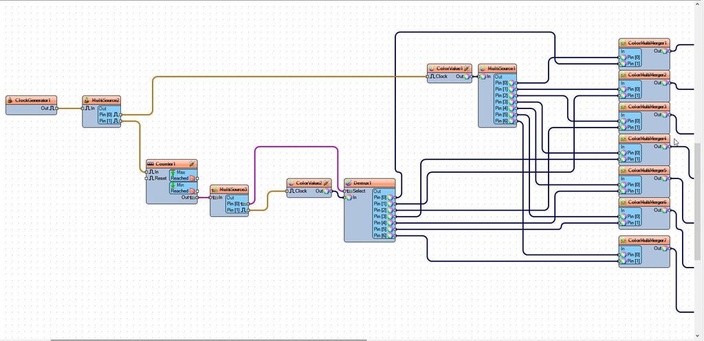
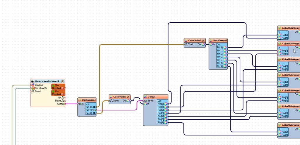
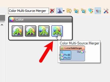
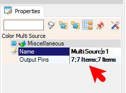
Connect "MultiSource1" pin [0] to "ColorMultiMerger1" pin [0]Connect "MultiSource1" pin [1] to "ColorMultiMerger2" pin [0]Connect "MultiSource1" pin [2] to "ColorMultiMerger3" pin [0]Connect "MultiSource1" pin [3] to "ColorMultiMerger4" pin [0]Connect "MultiSource1" pin [4] to "ColorMultiMerger5" pin [0]Connect "MultiSource1" pin [5] to "ColorMultiMerger6" pin [0]Connect "MultiSource1" pin [6] to "ColorMultiMerger7" pin [0]
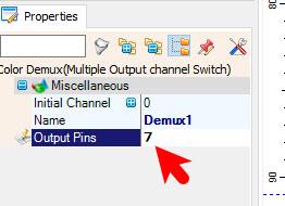
Connect "Demux1" pin [0] to "ColorMultiMerger1" pin [1]Connect "Demux1" pin [1] to "ColorMultiMerger2" pin [1]Connect "Demux1" pin [2] to "ColorMultiMerger3" pin [1]Connect "Demux1" pin [3] to "ColorMultiMerger4" pin [1]Connect "Demux1" pin [4] to "ColorMultiMerger5" pin [1]Connect "Demux1" pin [5] to "ColorMultiMerger6" pin [1]Connect "Demux1" pin [6] to "ColorMultiMerger7" pin [1]
Connect "ColorMultiMerger1" pin [Out] to "MultiSource4" pin [In]Connect "ColorMultiMerger2" pin [Out] to "MultiSource5" pin [In]Connect "ColorMultiMerger3" pin [Out] to "MultiSource6" pin [In]Connect "ColorMultiMerger4" pin [Out] to "MultiSource7" pin [In]Connect "ColorMultiMerger5" pin [Out] to "MultiSource8" pin [In]Connect "ColorMultiMerger6" pin [Out] to "MultiSource9" pin [In]Connect "ColorMultiMerger7" pin [Out] to "MultiSource10" pin [In]
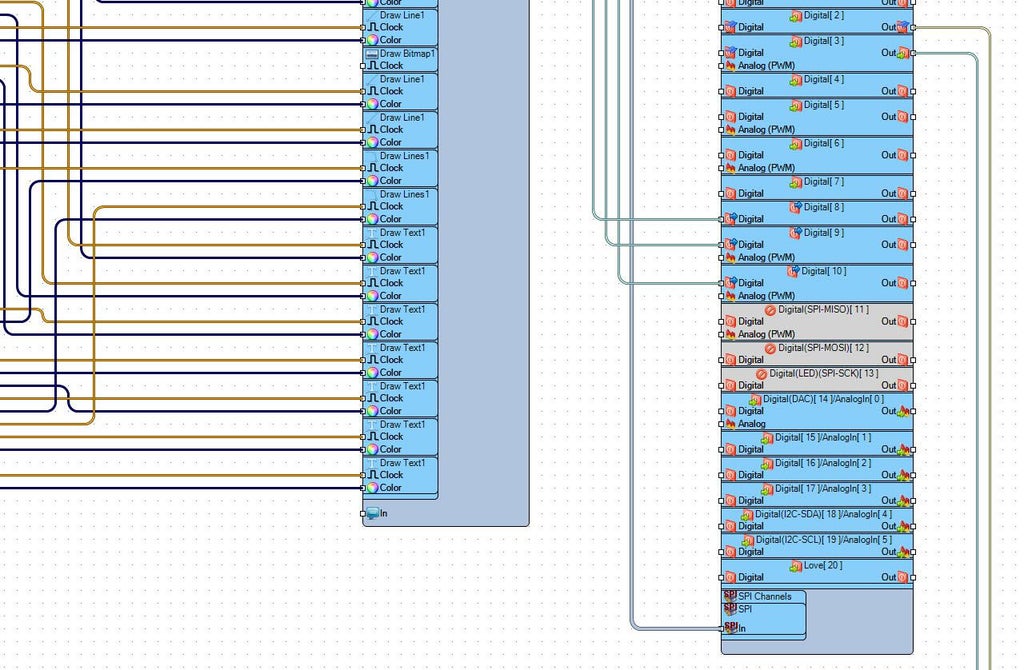
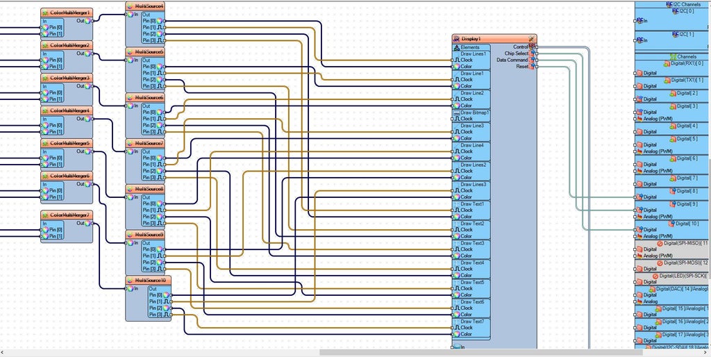
Connect "MultiSource4" pin [0] to "Display1" > "Draw Lines1" pin [Color]Connect "MultiSource4" pin [1] to "Display1" > "Draw Lines1" pin [Clock]Connect "MultiSource4" pin [2] to "Display1" > "Draw Text1" pin [Color]Connect "MultiSource4" pin [3] to "Display1" > "Draw Text1" pin [Clock]Connect "MultiSource5" pin [0] to "Display1" > "Draw Line1" pin [Color]Connect "MultiSource5" pin [1] to "Display1" > "Draw Line1" pin [Clock]Connect "MultiSource5" pin [2] to "Display1" > "Draw Text2" pin [Color]Connect "MultiSource5" pin [3] to "Display1" > "Draw Text2" pin [Clock]Connect "MultiSource6" pin [0] to "Display1" > "Draw Line2" pin [Color]Connect "MultiSource6" pin [1] to "Display1" > "Draw Line2" pin [Clock]Connect "MultiSource6" pin [2] to "Display1" > "Draw Text3" pin [Color]Connect "MultiSource6" pin [3] to "Display1" > "Draw Text3" pin [Clock]Connect "MultiSource7" pin [0] to "Display1" > "Draw Line3" pin [Color]Connect "MultiSource7" pin [1] to "Display1" > "Draw Line3" pin [Clock]Connect "MultiSource7" pin [2] to "Display1" > "Draw Text4" pin [Color]Connect "MultiSource7" pin [3] to "Display1" > "Draw Text4" pin [Clock]Connect "MultiSource8" pin [0] to "Display1" > "Draw Line4" pin [Color]Connect "MultiSource8" pin [1] to "Display1" > "Draw Line4" pin [Clock]Connect "MultiSource8" pin [2] to "Display1" > "Draw Text5" pin [Color]Connect "MultiSource8" pin [3] to "Display1" > "Draw Text5" pin [Clock]Connect "MultiSource9" pin [0] to "Display1" > "Draw Lines2" pin [Color]Connect "MultiSource9" pin [1] to "Display1" > "Draw Lines2" pin [Clock]Connect "MultiSource9" pin [2] to "Display1" > "Draw Text6" pin [Color]Connect "MultiSource9" pin [3] to "Display1" > "Draw Text6" pin [Clock]Connect "MultiSource10" pin [0] to "Display1" > "Draw Lines3" pin [Color]Connect "MultiSource10" pin [1] to "Display1" > "Draw Lines3" pin [Clock]Connect "MultiSource10" pin [2] to "Display1" > "Draw Text7" pin [Color]Connect "MultiSource10" pin [3] to "Display1" > "Draw Text7" pin [Clock]
Connect "Display1" pin [Chip Select] to Arduino digital pin [10]Connect "Display1" pin [Data Command] to Arduino digital pin [9]Connect "Display1" pin [Reset] to Arduino digital pin [8]Connect "Display1" Control pin [SPI] to Arduino SPI pin [In]
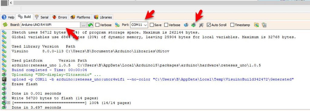
In Visuino, at the bottom click on the "Build" Tab, make sure the correct port is selected, then click on the "Compile/Build and Upload" button.
If you power the Arduino module, The Display will show the Gear shift and if you use Rotary Encoder, you can change the gear on the Display.
I hope that this guide will serve you as an inspiration for your future projects.
Congratulations! You have completed your project with Visuino. Also attached is the Visuino project, that I created for this tutorial, you can download it and open it in Visuino: https://www.visuino.eu