Arduino OLED Countdown Timer Using Visual Programming

Build a compact and practical OLED Countdown Timer using Arduino and Visual Programming in Visuino!

Use a rotary encoder to set the countdown durationStart the timer by pressing the encoder buttonWatch the countdown update in real time on an OLED displayTrigger a Red LED when the countdown reaches zero

All done with no coding, just simple drag-and-drop blocks in Visuino!

Perfect for beginners and makers looking for a practical timer easy to build.

Watch the Video!

STEP 1
What You Will Need


What You Will Need

What You Will Need

What You Will Need

What You Will Need

What You Will Need

What You Will Need

Arduino UNO or any other Arduino boardBreadboardOLED Display1k ohm resistorLEDRotary encoderJumper wiresVisuino software: Download here


STEP 2
The Circuit

The Circuit

🔌 OLED Display Connections

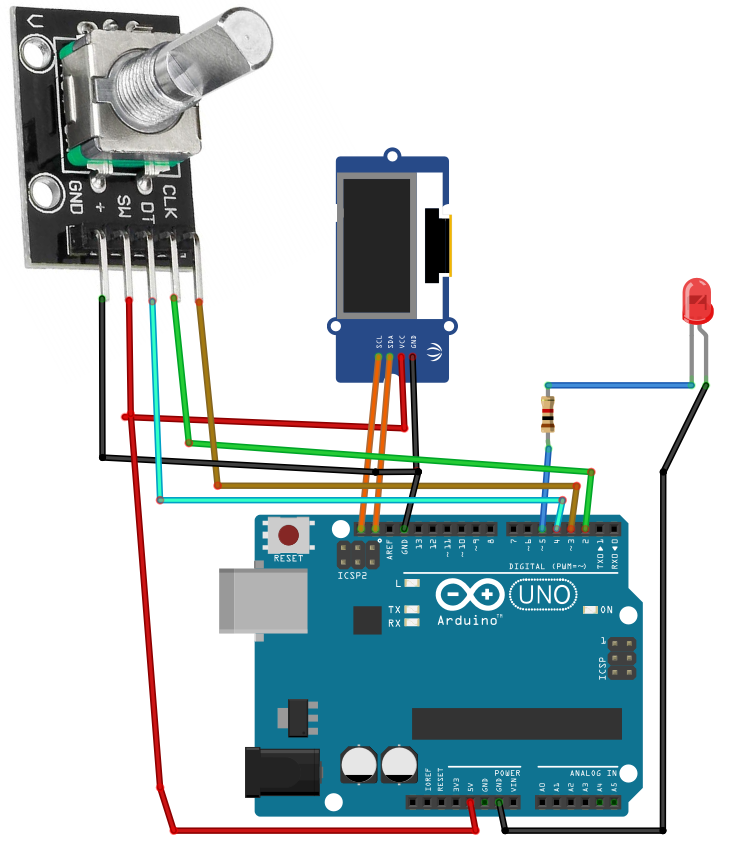
Connect OLED Display pin [SCL] to Arduino pin [SCL]Connect OLED Display pin [SDA] to Arduino pin [SDA]Connect OLED Display pin [VCC] to Arduino pin [5V]Connect OLED Display pin [GND] to Arduino pin [GND]

🔄 Rotary Encoder Module Connections

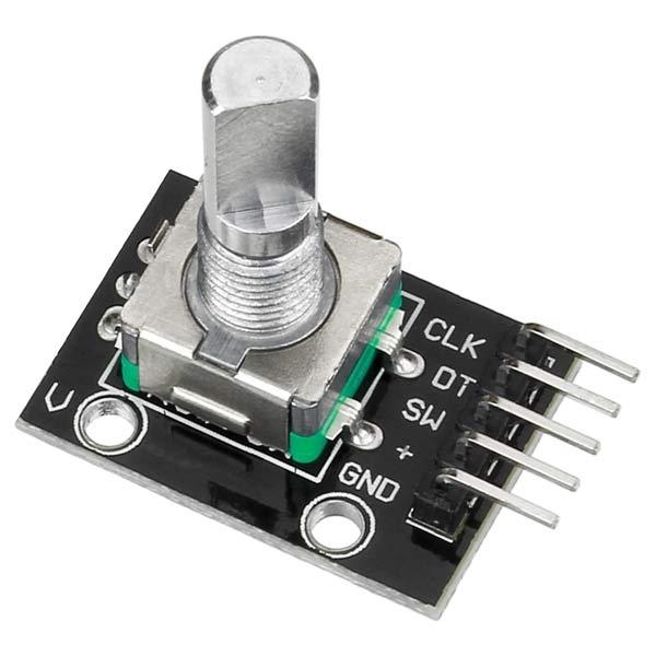
Connect Encoder pin [CLK] to Arduino pin [3]Connect Encoder pin [DT] to Arduino pin [2]Connect Encoder pin [SW] to Arduino pin [4]Connect Encoder pin [+ (VCC)] to Arduino pin [5V]Connect Encoder pin [GND] to Arduino pin [GND]

🔴 LED Output Connection

Connect 220Ω resistor to Arduino pin [5]Connect anode (long leg) of Red LED to the resistorConnect cathode (short leg) of LED to Arduino [GND]


STEP 3
Start Visuino, and Select the Arduino UNO Board Type

Start Visuino, and Select the Arduino UNO Board Type

Start Visuino, and Select the Arduino UNO Board Type

The Visuino: https://www.visuino.com also needs to be installed.

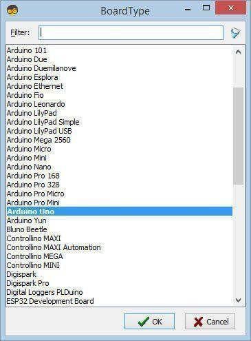
Start Visuino as shown in the first picture Click on the "Tools" button on the Arduino component (Picture 1) in Visuino When the dialog appears, select "Arduino UNO" as shown on Picture 2

STEP 4
In Visuino Add Components

In Visuino Add Components

In Visuino Add Components

In Visuino Add Components

In Visuino Add Components

In Visuino Add Components

In Visuino Add Components

In Visuino Add Components

In Visuino Add Components

In Visuino Add Components

In Visuino Add Components

In Visuino Add Components

In Visuino Add Components

In Visuino Add Components

In Visuino Add Components

Add "OLED I2C" componentAdd "Debounce Button" componentAdd "Digital (Boolean) Inverter (Not)" componentAdd 2X "Digital Multi Source" componentAdd "Rotary Encoder" componentAdd "Toggle(T) Flip-Flop" componentAdd "Pulse Generator" componentAdd 3X "Integer Multi Source" componentAdd 2X "Integer Multi-Source Merger" componentAdd "Up/Down Counter" componentAdd "Divide Integer By Value" componentAdd "Multiply Integer By Value" componentAdd "Subtract Integer Value" componentAdd "Formatted Text" component
STEP 5
In Visuino Set Components

In Visuino Set Components

In Visuino Set Components

In Visuino Set Components

In Visuino Set Components

In Visuino Set Components

In Visuino Set Components

In Visuino Set Components

In Visuino Set Components

In Visuino Set Components

In Visuino Set Components

In Visuino Set Components

In Visuino Set Components

Select "MultiSource1" and in the properties window set "Output Pins" to 3Select "UpDownCounter1" and in the properties window select:"Initial Value" and set 10and set "Max > Roll Over" to False and "Min > Roll Over" to False and Min Value to 0.Select "PulseGenerator1" and in the properties window Select "Enabled" and click on the pin icon and select "Boolean SinkPin" and set "Enabled" to FalseSelect "MultiSource2" and in the properties window set "Output Pins" to 3Select "RotaryEncoderSensor1" and in the properties window select:"Initial Value" and set 10 and set "Max > Roll Over" to False and "Min > Roll Over" to False and Min Value to 0.Select "DivideByValue1" and in the properties window set Value to 60Select "MultiplyByValue1" and in the properties window set Value to 60Select "SubtractValue1" and in the properties window select Value and click on the Pin Icon and select "Integer SinkPin"Select "FormattedText1" and in the properties window set "Text" to: %0:%1Double click on "FormattedText1" and in the Elements window drag 2X "Text Element" to the left side and for both in the Properties window set "Fill Character" to 0 and "Length" to 2Double click on "DisplayOLED1" and in the Elements window drag "Text Field" to the left side and in the properties window set "Size" to 2 "X" to 30 and "Y" to 20
STEP 6
In Visuino Connect Components
Connect Arduino digital pin [2] to "RotaryEncoder1" pin Clock (A)Connect Arduino digital pin [3] to "RotaryEncoder1" pin Data (B)Connect Arduino digital pin [4] to "Button1" pin [In]Connect "Button1" pin [Out] to "Inverter1" pin [In]Connect "Inverter1" pin [Out] to "MultiSource1" pin [In]Connect "MultiSource1" pin [Out][0] to "UpDownCounter1" pin [Reset]Connect "MultiSource1" pin [Out][1] to "FormattedText1" pin [Clock]Connect "MultiSource1" pin [Out][2] to "TFlipFlop1" pin [Clock]Connect "DivideByValue1" pin [Out] to "IntegerMultiSource1" pin [In]Connect "IntegerMultiSource1" pin [Out][0] to "FormattedText1" pin [Clock]Connect "IntegerMultiSource1" pin [Out][0] to "FormattedText1" > "TextElement1" pin [In]Connect "IntegerMultiSource1" pin [Out][1] to "MultiplyByValue1" pin [In]Connect "MultiplyByValue1" pin [Out] to "SubtractValue1" pin [Value]Connect "SubtractValue1" pin [Out] to "FormattedText1" pin [Clock]Connect "SubtractValue1" pin [Out] to "FormattedText1" > "TextElement2" pin [In]Connect "FormattedText1" pin [Out] to "DisplayOLED1" > "Text Field1" pin [Clock]Connect "FormattedText1" pin [Out] to "DisplayOLED1" > "Text Field1" pin [In]Connect "DisplayOLED1" pin [Out] to "Arduino" > "I2C" pin [In]Connect "UpDownCounter1" pin [Out] to "IntegerMultiMerger1" pin [In][0]Connect "IntegerMultiMerger1" pin [Out] to "IntegerMultiSource2" pin [In]Connect "IntegerMultiSource2" pin [Out][0] to "DivideByValue1" pin [In]Connect "IntegerMultiSource2" pin [Out][1] to "SubtractValue1" pin [In]Connect "IntegerMultiSource2" pin [Out][2] to "CompareValue1" pin [In]Connect "IntegerMultiSource2" pin [Out][3] to "FormattedText1" pin [Clock]Connect "CompareValue1" pin [Out] to "Arduino" digital pin [5]Connect "PulseGenerator1" pin [Out] to "DigitalMultiSource1" pin [In]Connect "DigitalMultiSource1" pin [Out][0] to "UpDownCounter1" pin [Down]Connect "DigitalMultiSource1" pin [Out][1] to "FormattedText1" pin [Clock]Connect "RotaryEncoderSensor1" pin [Out] to "MultiSource2" pin [In]Connect "MultiSource2" pin [Out][0] to "IntegerMultiMerger1" pin [In][1]Connect "MultiSource2" pin [Out][1] to "UpDownCounter1" pin [Reset]Connect "MultiSource2" pin [Out][2] to "UpDownCounter1" pin [InitialValue]Connect "TFlipFlop1" pin [Out] to "PulseGenerator1" pin [Enabled]Connect "UpDownCounter1" pin [MinReached] to "TFlipFlop1" pin [Reset]
STEP 7
Generate, Compile, and Upload the Arduino Code

Generate, Compile, and Upload the Arduino Code

In Visuino, at the bottom click on the "Build" Tab, make sure the correct port is selected, then click on the "Compile/Build and Upload" button.

STEP 8
Play

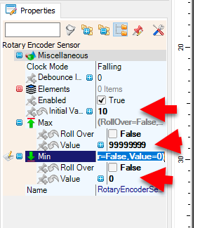
When you power on the Arduino, the OLED display will show the default countdown time of 00:10.

You can easily adjust the countdown time by rotating the rotary encoder left or right. Once you've set your desired time, simply press the encoder button to start the countdown.

During the countdown, you can pause or resume at any time by pressing the button again.

When the countdown reaches zero, a red LED will turn ON to signal that the time is up.


Congratulations! You have completed your project with Visuino. Also attached is the Visuino project, that I created for this Instructable, you can download it and open it in Visuino: https://www.visuino.com

icon OLED-CountDown-Timer-Encoder.zip 2KB Download(0)
License
All Rights
Reserved
licensBg
0