How to Automate Linear Actuator Using Arduino & Visual Programming

In this step-by-step tutorial, you’ll discover how to create sequences that control your actuator with precise timing (in milliseconds or even microseconds). You’ll also see how to set the speed and direction of movement, giving you complete automation control. Perfect for beginners and advanced makers, this project shows just how easy it is to bring your actuator to life with Arduino + Visuino visual programming.

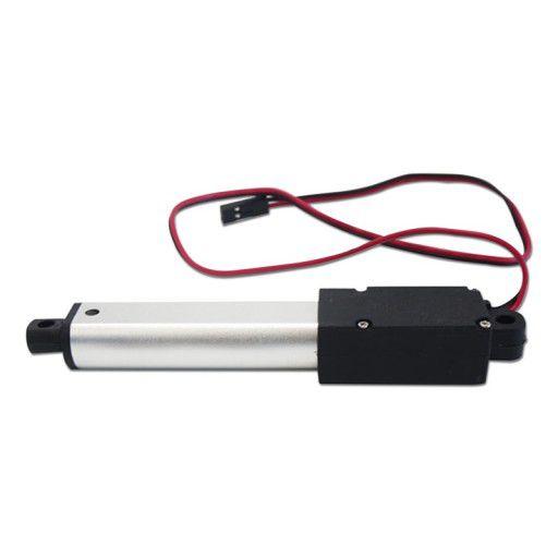
Step 1: What You Will Need

What You Will Need

What You Will Need

What You Will Need

What You Will Need

What You Will Need

What You Will Need

Arduino UNO (Or any other Arduino)Linear ActuatorLN298N DC Motor DriverJumper wiresPower SupplyVisuino program: Download Visuino

Ā 

Step 2: The Circuit

The Circuit

Connect Power supply (batteries) pin (gnd) to motor driver controler pin (gnd)Connect Power supply (batteries) pin (+) to motor driver controler pin (+)Connect Power supply (batteries) pin (+) to Arduino pin (VIN)Connect GND from Arduino to motor driver controler pin (gnd)Connect digital pin(6) from Arduino to motor driver pin (IN1)Connect digital pin(8) from Arduino to motor driver pin (IN2)Connect Linear Actuator to the motor driver as you can see on the schematic

Ā 

Step 3: Start Visuino, and Select the Arduino UNO Board Type

Start Visuino, and Select the Arduino UNO Board Type

Start Visuino, and Select the Arduino UNO Board Type

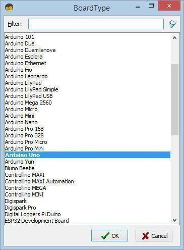
Start Visuino as shown in the first picture Click on the "Tools" button on the Arduino component (Picture 1) in Visuino When the dialog appears, select "Arduino UNO" as shown on Picture 2

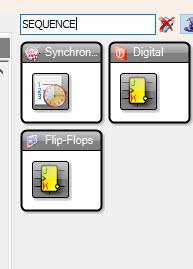
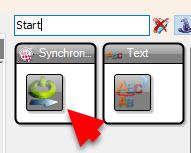
Step 4: In Visuino Add Components

In Visuino Add Components

In Visuino Add Components

In Visuino Add Components

In Visuino Add Components

In Visuino Add Components

In Visuino Add Components

Add "Sequence" componentAdd "Analog Value" componentAdd "Start" componentAdd "Toggle(T) Flip-Flop" componentAdd "Speed and Direction To Speed" componentAdd "Dual DC Motor Driver Digital and PWM Pins Bridge (L9110S, L298N)" component

Step 5: In Visuino Set Components

In Visuino Set Components

In Visuino Set Components

In Visuino Set Components

In Visuino Set Components

In Visuino Set Components

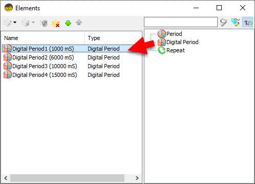
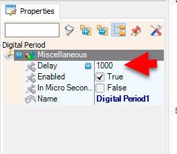
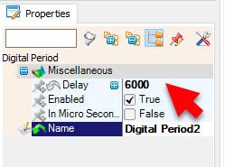
Double click on the "Sequence1" and in the Elements window drag to the left as many "Digital period" elements as you like, in this example we will add 4 "Digital period" elements and for each we will set the Delay in the properties window:

Digital Period1: 1000Digital Period2: 6000Digital Period3: 10000Digital Period4: 15000

Ā 

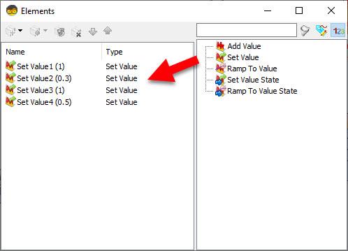
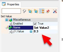
Double click on the "AnalogValue1" and in the Elements window drag to the left as many "Set Value" elements as you like, in this example we will add 4 "Set Value" elements and for each we will set the Value in the properties window:

Set Value1: 1000Set Value2: 6000Set Value3: 10000Set Value4: 15000

Ā 

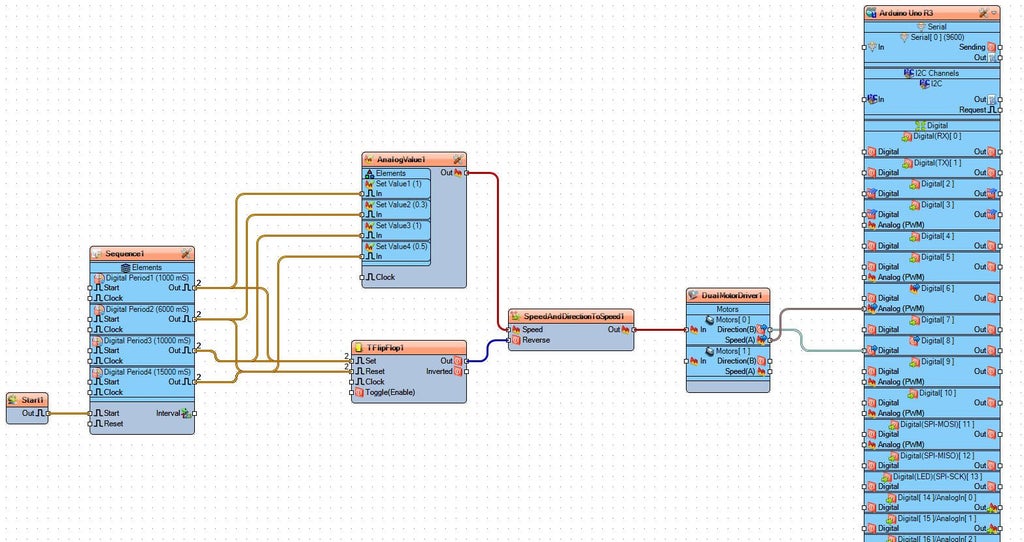
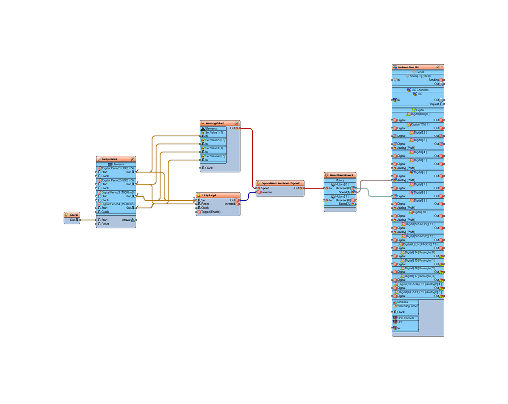
Step 6: In Visuino Connect Components

Connect "Start1" pin [Out] to "Sequence1" pin [Start]Connect "Sequence1" > "DigitalPeriod1" pin [Out] to "AnalogValue1" > "Set Value1" pin [In]Connect "Sequence1" > "DigitalPeriod1" pin [Out] to "TFlipFlop1" pin [Set]Connect "Sequence1" > "DigitalPeriod2" pin [Out] to "AnalogValue1" > "Set Value2" pin [In]Connect "Sequence1" > "DigitalPeriod2" pin [Out] to "TFlipFlop1" pin [Reset]Connect "Sequence1" > "DigitalPeriod3" pin [Out] to "AnalogValue1" > "Set Value3" pin [In]Connect "Sequence1" > "DigitalPeriod3" pin [Out] to "TFlipFlop1" pin [Set]Connect "Sequence1" > "DigitalPeriod4" pin [Out] to "AnalogValue1" > "Set Value4" pin [In]Connect "Sequence1" > "DigitalPeriod4" pin [Out] to "TFlipFlop1" pin [Reset]Connect "AnalogValue1" pin [Out] to "SpeedAndDirectionToSpeed1" pin [Speed]Connect "TFlipFlop1" pin [Out] to "SpeedAndDirectionToSpeed1" pin [Reverse]Connect "SpeedAndDirectionToSpeed1" pin [Out] to "DualMotorDriver1" > [Motors.Item[0] pin [In]Connect "DualMotorDriver1" > [Motors.Item[0].Direction] pin [Out] to "Arduino" pin Digital pin [8]Connect "DualMotorDriver1" > [Motors.Item[0].Speed] pin [Out] to "Arduino" pin Digital > Analog PWM pin [6]

Ā 

Ā 

Step 7: Generate, Compile, and Upload the Arduino Code

Generate, Compile, and Upload the Arduino Code

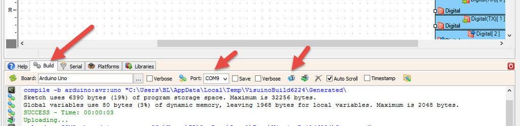
In Visuino, at the bottom click on the "Build" Tab, make sure the correct port is selected, then click on the "Compile/Build and Upload" button.

Ā 

Ā 

Step 8: Play

If you power the Arduino module and the Linear Actuator will start to move according to your settings..

Congratulations! You have completed your project with Visuino. Also attached is the Visuino project, that I created for this tutorial, you can download it here and open it in Visuino: https://www.visuino.eu

Ā 

Download Visuino file: Linear-Actuator-Sequence.visuino

License
All Rights
Reserved
licensBg
0