Build Arduino RFID Door Lock With Visual Programming (Visuino + MFRC522)

Create a secure Arduino RFID Door Lock with Visual Programming in Visuino! This tutorial shows how to connect the MFRC522 RFID module, check RFID card IDs, and control a magnetic solenoid lock. When a valid RFID card is detected, the door unlocks and a green LED lights up as a visual confirmation. Swipe the same card again to lock the door. Unauthorized cards are denied access.
🔹 What you’ll learn:
Wiring and configuring MFRC522 with ArduinoUsing Visual Programming in Visuino to detect RFID card UIDsChecking IDs against an authorized list (access control)Controlling a solenoid lock with Arduino + VisuinoAdding a green LED indicator for successful unlockImplementing re-swipe toggle logic (lock again)🔹 Hardware Required:
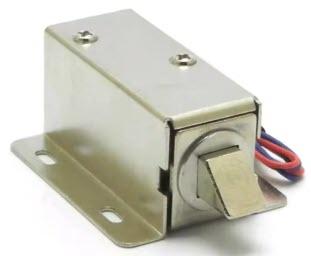
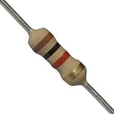
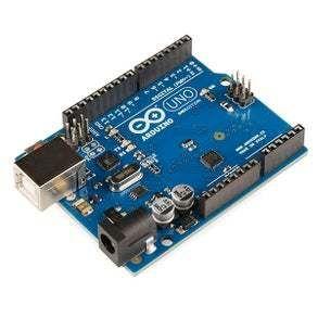
Arduino board (Uno, Nano, Mega, or compatible)MFRC522 RFID module + RFID tags/cardsMagnetic solenoid lock (or electric strike) with driver (relay/MOSFET)Green LED + resistor (for unlock indication)External power supply for solenoidBreadboard, jumper wires, optional buzzer🔹 Why this project is great:
No coding — 100% Visual Programming with VisuinoBeginner-friendly but practical for smart home securityIncludes both lock control and LED feedback for clear status
Watch the Video!
Step 1: What You Will Need


Step 2: The Circuit
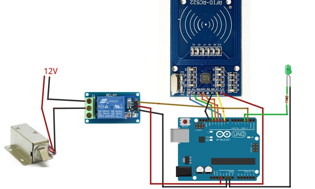
Connect Arduino digital pin [3] to 1K ohm resistorConnect 1K ohm resistor to LED positive pin (+)Connect LED negative pin (-) to Arduino Pin GND
Connect Relay VCC pin(+) to Arduino 5V pinConnect Relay GND pin(-) to Arduino GND pinConnect Relay signal pin(S) to Arduino Digital pin 2Connect power supply 12V (+) to Electromagnetic lock red wire(+)Connect power supply 12V (-) to relay pin(com)Connect Electromagnetic lock black wire (-) to relay pin(NO)
Step 3: Start Visuino, and Select the Arduino UNO Board Type

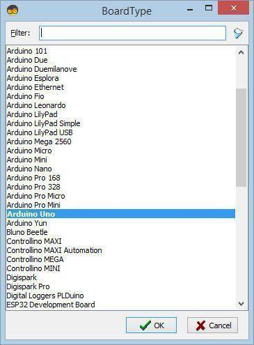
Start Visuino as shown in the first picture Click on the "Tools" button on the Arduino component (Picture 1) in Visuino When the dialog appears, select "Arduino UNO" as shown on Picture 2
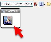
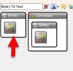
Step 4: In Visuino Add Components


Step 5: In Visuino Set Components
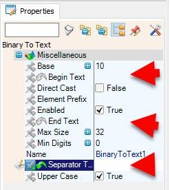

Select "BinaryToText1" and in the properties window set "Begin Text", "End Text" and "Separator Text" to empty
Select "TextValue1" and in the properties select "Value", click on the 3 dots button and in the Value window set you card IDs
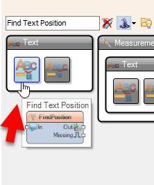
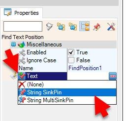
Select "FindPosition1" and in the properties window select "Text", click on the pin icon and select "String SinkPin"
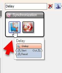
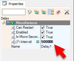
Select "Delay1" and in the properties window set "Interval" to 500000 (0.5s) you can adjust this value according to your needs, in this project it is used to add a small delay in reading the RFID tag to prevent double reading when you swipe the tag.
Step 6: In Visuino Connect Components
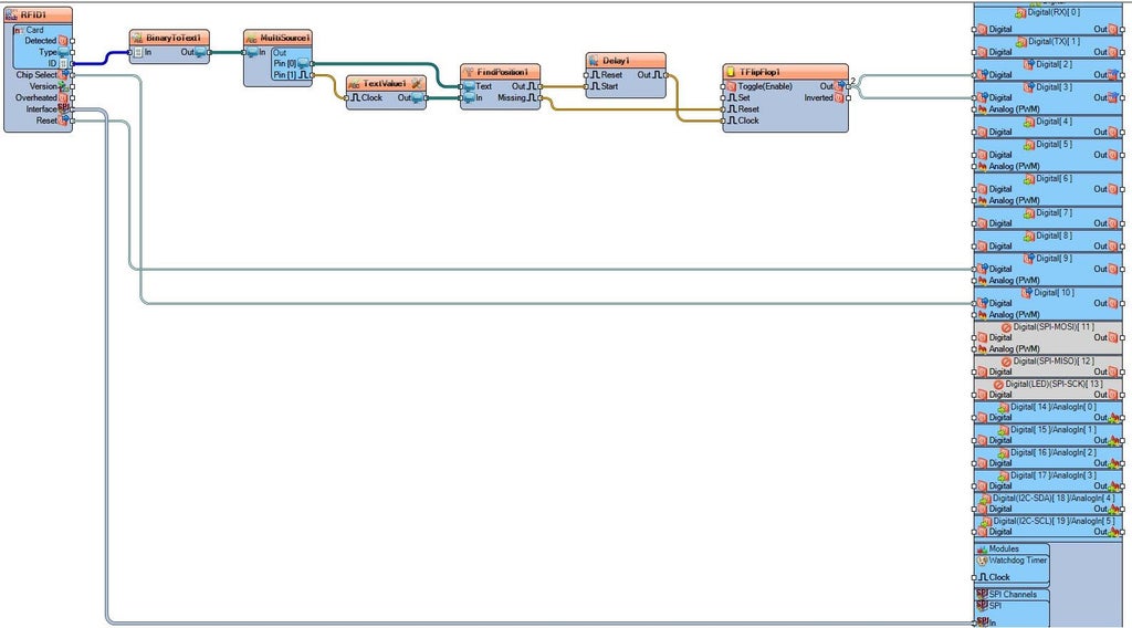
Connect (Byte) from RFID1.Card.ID OutputPin to BinaryToText1.InputPinConnect (Digital Output Pin) from RFID1.ChipSelect OutputPin to Arduino.Digital.Digital[ 10 ].DigitalInputPinConnect (SPI Communication) from RFID1.Interface OutputPin to Arduino.SPIChannels.SPI.InputPinConnect (Digital Output Pin) from RFID1.Reset OutputPin to Arduino.Digital.Digital[ 9 ].DigitalInputPin
Connect (Sting) from BinaryToText1.OutputPin to MultiSource1.InputPinConnect (Sting) from MultiSource1.OutputPins.Pin [0] to FindPosition1.TextConnect (Clock) from MultiSource1.OutputPins.Pin [1] to TextValue1.Clock InputPinConnect (Sting) from TextValue1.OutputPin to FindPosition1.InputPin
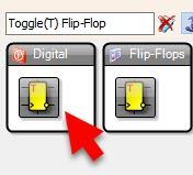
Connect (Clock) from FindPosition1.OutputPin to Delay1.Start InputPinConnect (Clock) from FindPosition1.Missing OutputPin to TFlipFlop1.Reset InputPinConnect (Clock) from Delay1.OutputPin to TFlipFlop1 ClockInputPinConnect TFlipFlop1.OutputPin to MultiSource2.InputPinConnect MultiSource2.OutputPins.Pin [0] to Arduino.Digital.Digital[ 2 ].DigitalInputPinConnect MultiSource2.OutputPins.Pin [1] to Arduino.Digital.Digital[ 3 ].DigitalInputPin
Step 7: Generate, Compile, and Upload the Arduino Code
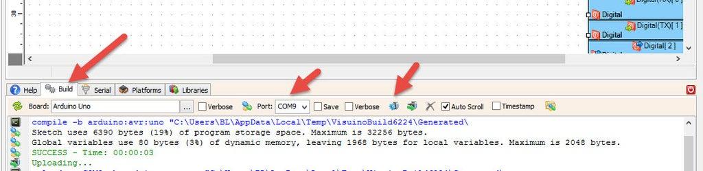
In Visuino, at the bottom click on the "Build" Tab, make sure the correct port is selected, then click on the "Compile/Build and Upload" button.
Step 8: Play
Congratulations! You have completed your project with Visuino. Also attached is the Visuino project, that I created for this Instructable, you can download it and open it in Visuino: https://www.visuino.eu
Download Visuino file: RFID-Lock.visuino


