

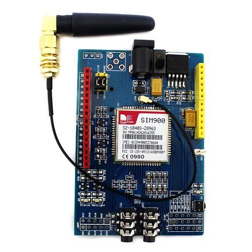
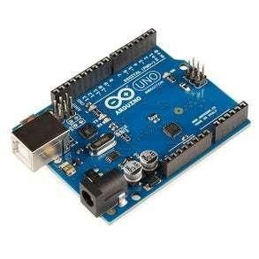
In this tutorial we are going to make an Arduino GSM Clock ⏰ that gets the current Date and Time automatically from the mobile network, using an Arduino Uno, the SIM900 GSM Shield, an LCD display, and Visuino.
Why is this project better than most of the "Arduino Clock" projects out there? Because usually you need an RTC module, a Wi-Fi connection, or even internet access just to keep the correct time. Here we don't need any of that — the SIM900 pulls the Date, Time, and Time Zone straight from the GSM mobile network itself.
📌 On this project, the SIM900 GSM module receives the time information directly from a supported GSM mobile network, and as soon as it synchronizes, the Arduino simply asks it for the current time using AT commands and displays it on the LCD screen.
📌 We will connect and configure the SIM900 GSM Shield with the Arduino, enable the automatic GSM network time synchronization with the AT+CLTS=1 command, and then retrieve the Date and Time with AT+CCLK?.
📌 In Visuino we will use the Software Serial and Char To Text components to communicate with the SIM900, receive the serial data, and process the network time information so it can be displayed on the LCD.
📌 One of the best things about this project is that the clock sets itself — the moment the GSM module starts and connects to a mobile network that provides time synchronization, it grabs the correct Date and Time on its own. So no more manually setting the clock after every restart.
📌 This project can be used as a base for Arduino digital clocks, GSM data logging systems, remote monitoring stations, industrial automation, security systems, automatic scheduling, and IoT projects that need Date and Time information without relying on Wi-Fi or an external RTC module.
Watch the Video!
Also check out this tutorial: Make a Phone Call Using the SIM900 GSM Shield & Arduino - Visuino Tutorial
- SIM900 GSM Shield
- Arduino UNO
- Sim card (You should disable the pin request on the sim card before using it with the GSM shield)
- LCD 16X2 I2C or ano other LCD
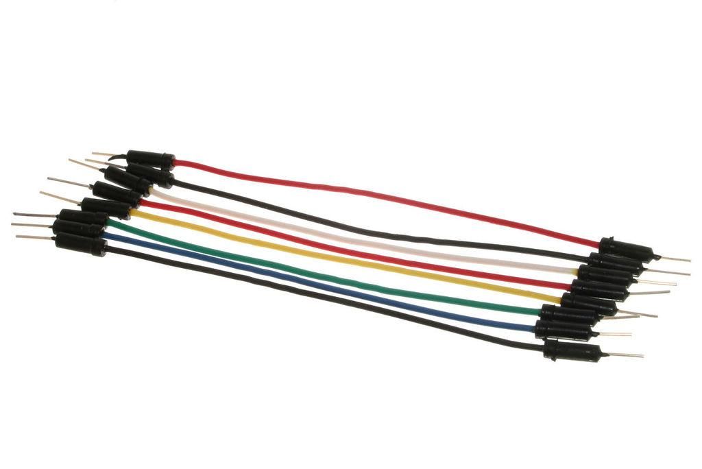
- Jumper wires
- 5V power supply with enough amps for the shield
- Visuino program: Download Visuino

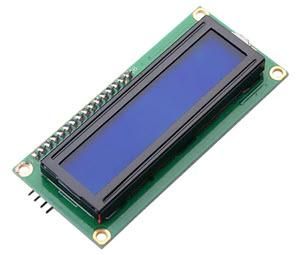
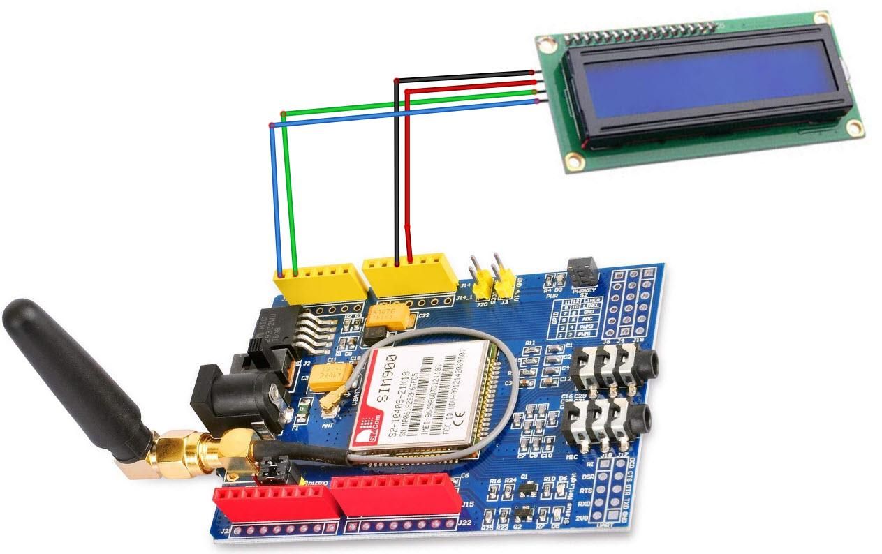
- Connect LCD pin (VCC) TO GSM Shield pin (5V)
- Connect LCD pin (GND) TO GSM Shield pin (GND)
- Connect LCD pin (SCL) TO GSM Shield pin (A5)
- Connect LCD pin (SDA) TO GSM Shield pin (A4)
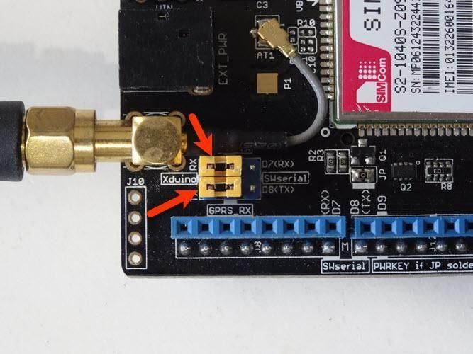
- Connect with the Jumpers on the shield pins D8(RX) & D7(TX) like you see it on the picture
- Make sure that the antenna is connected to the shield
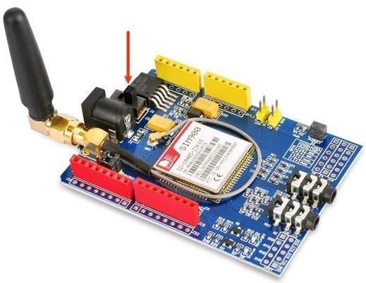
- Connect the 5V Power Supply to the shield, and set the switch on the shield to the External Power (See the picture)
- Once the Power is connected hold the Power button for 2s
- Once the connection with the Network is established the LED will blink every 3s
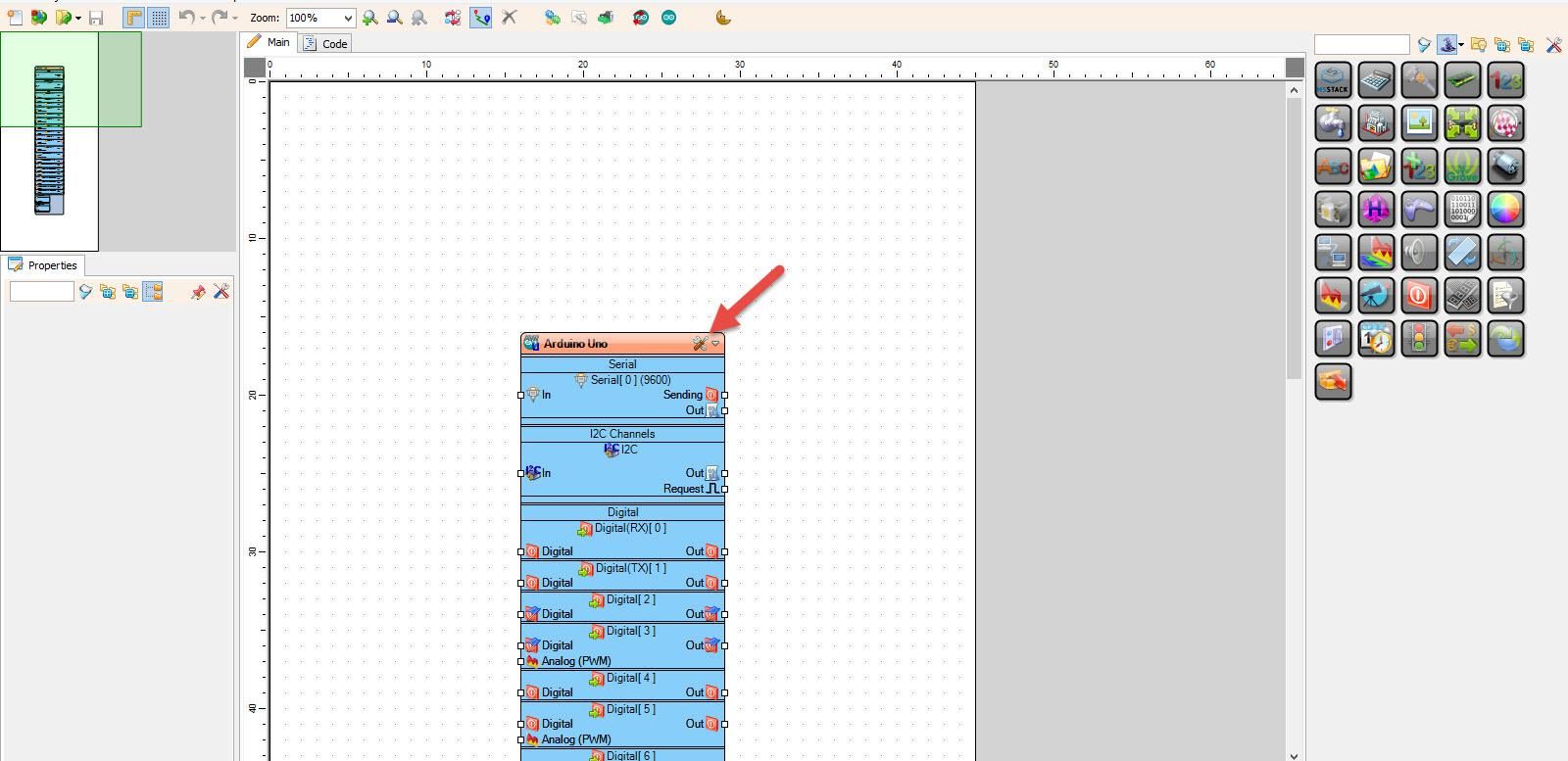
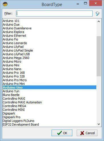
Start Visuino as shown in the first picture Click on the "Tools" button on the Arduino component (Picture 1) in Visuino When the dialog appears, select "Arduino UNO" as shown on Picture 2
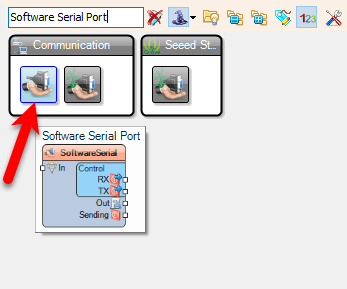
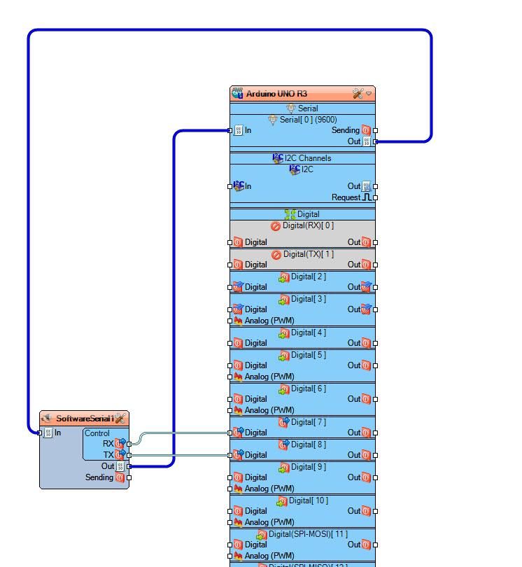
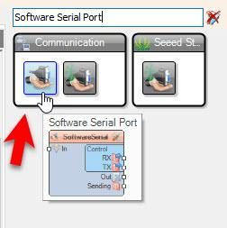
- Add "Software Serial Port" component
- Connect "SoftwareSerial1" pin [RX] to Arduino Digital pin [7]
- Connect "SoftwareSerial1" pin [TX] to Arduino Digital pin [8]
- Connect Arduino serial pin [Out] to "SoftwareSerial1" pin [In]
- Connect "SoftwareSerial1" to Arduino serial pin [In]
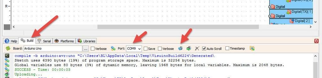
In Visuino, at the bottom click on the "Build" Tab, make sure the correct port is selected, then click on the "Compile/Build and Upload" button.
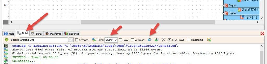
When you power the Shield wait a bit for the connection with the network to be established, once the connection is established the LED on the shield will blink every 3s.
Open the Serial Monitor
In Visuino Open under Serial tab select the correct COM port and click Connect button.
The Serial connection in this project is set to 9600 baud.
After the SIM900 starts, you should see messages similar to:
RDY
+CFUN: 1
+CPIN: READY
Call Ready
In the Serial Terminal window, type:
AT+CLTS=1
This will enable automatic date and time synchronization from the mobile network.
Restart SIM900 by turning it Off and back On, You can also in serial window click Disconnect button and again Connect button.
Now in serial window type:
AT+CCLK?
If your mobile operator supports automatic GSM network time synchronization, you should see messages similar to this:
+CCLK: "26/10/11,16:21:46+08"
OK
The information returned consists of:
- 26 – The year 2026
- 10 – The month of October
- 11 – The day of the month
- 16:21:46 – The present time (hours, minutes, and seconds)
- +08 – The time zone offset relative to UTC+2
The SIM900 encodes time zone offsets in 15-minute steps, which means +08 translates to 2 hours ahead of UTC.
After the SIM900 has updated its internal clock from the network, you can issue the AT+CCLK? command at any point to read back the current date and time.
Since the clock keeps ticking on its own between queries, there is no need to resend the network synchronization command every time.
Verify the Output
When the SIM900 reports the accurate date and time, this confirms that synchronization with the GSM network time is functioning correctly, and we can move on to configuring Visuino to interpret the incoming data and show it on the LCD display.
However, if the response displays a wrong or factory-default date, for example:
+CCLK: "00/01/01,00:00:37+00"
the SIM900 has not yet received a valid time update from the network.
Verify that the SIM card is registered on the GSM network, that automatic synchronization has been turned on, and that your mobile carrier delivers network time information.
Note: Network time synchronization over GSM is dependent on your mobile carrier. The SIM900 is capable of receiving the date and time without requiring Wi-Fi, GPRS data, or an internet connection, but the carrier has to supply the required time information.
Having successfully verified both the serial communication and the GSM network time synchronization, we can now proceed to use Visuino components to extract the date and time and render them on the LCD screen.
Additional commands to try:
Test Communication with the SIM900
AT
The SIM900 should reply with:
AT
OK
Verify the SIM card status:
AT+CPIN?
Expected response:
+CPIN: READY OK
Confirm that the SIM900 has registered on the mobile network:
AT+CREG?
Sample response:
+CREG: 0,1 OK
Here, the value 1 means the module is registered on its home GSM network, while a value of 5 means it is registered while roaming.
To check the GSM signal quality, send:
AT+CSQ
Sample response:
+CSQ: 20,0 OK
The first number, ranging from 0 to 31, generally reflects signal strength — the higher the value, the better the reception.
Turn On Automatic Network Time Synchronization
To activate automatic date and time syncing from the mobile network, send:
AT+CLTS=1
Expected response:
OK
Turn Off Automatic Network Time Synchronization
To deactivate automatic date and time syncing from the mobile network, send:
AT+CLTS=0
Expected response:
OK
To confirm if the automatic date and time syncin is active, send:
AT+CLTS?
Expected response:
+CLTS: 1 OK
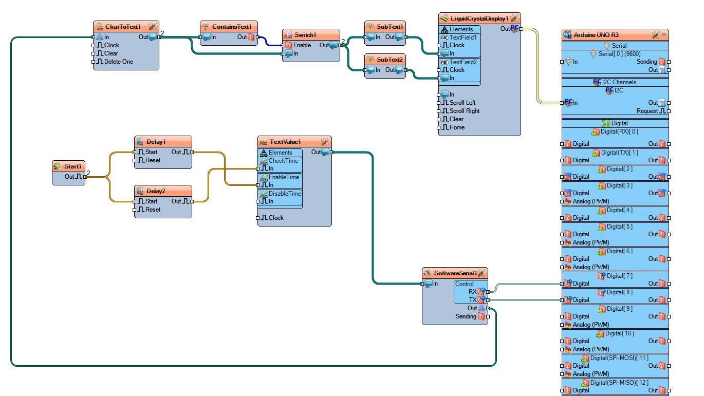
In this step, we will add an LCD display into our project and set it up in Visuino to show the current date and time received by the SIM900 GSM Shield.
- Add "Liquid Crystal Display (LCD) - I2C" component
- Add "Char To Text" component
- Add "Contains Text" component
- Add "Text On/Off Switch" component
- Add 2X "Extract Sub Text" component
- Add "Start" component
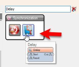
- Add 2X "Delay" component
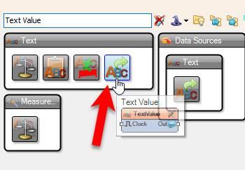
- Add "Text Value" component
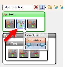
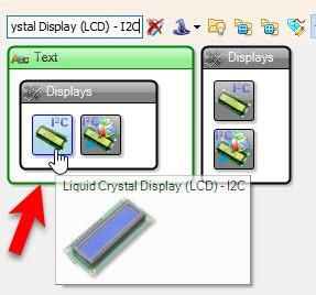
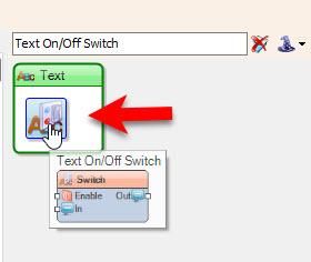
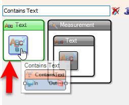
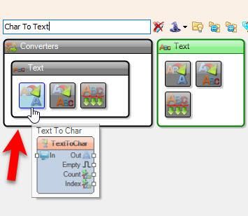
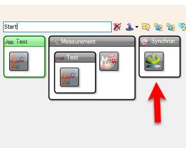
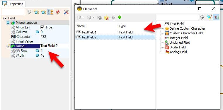
- Double click on the "LiquidCrystalDisplay1" and in the Elements window
- Drag "Text Field" element to the left side.
- Drag another "Text Field" element to the left side and in the properties window set "Row" to 1
- Close the Elements window
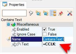
- Select "ContainsText1" and in the properties window set "Text" to +CCLK:
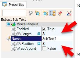
- Select "SubText1" and in the properties window set "Length" to 8 and "Position" to 8
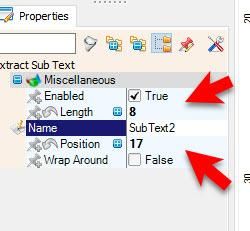
- Select "SubText2" and in the properties window set "Length" to 8 and "Position" to 17
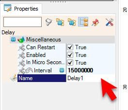
- Select "Delay1" and in the properties window set "Interval" to 15000000
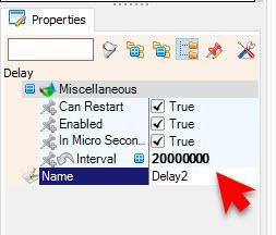
- Select "Delay2" and in the properties window set "Interval" to 20000000
- Double click on the "TextValue1" and in the Elements window
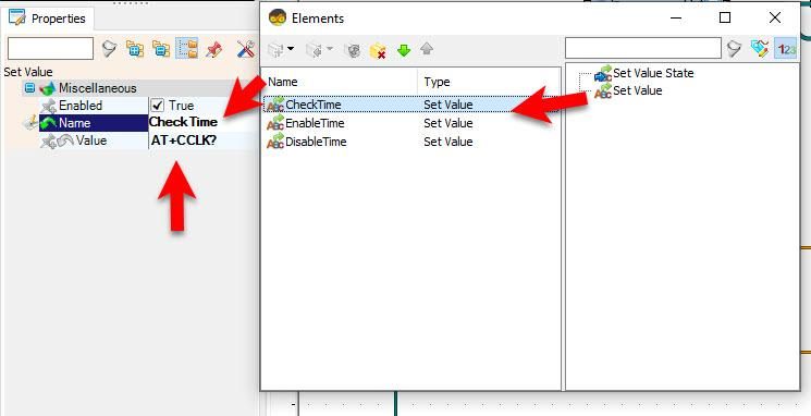
- Drag "Text Field" element to the left side and in the properties window set "Name" to CheckTime and "Value" to AT+CCLK?
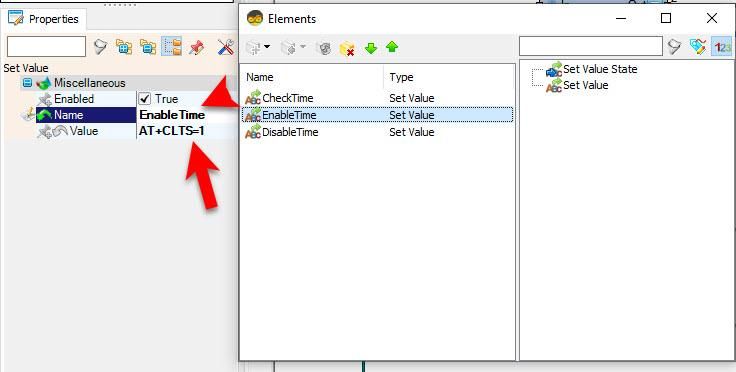
- Drag another "Text Field" element to the left side and in the properties window set "Name" to EnableTime and "Value" to AT+CLTS=1
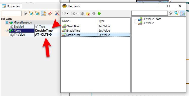
- Drag another "Text Field" element to the left side and in the properties window set "Name" to DisableTime and "Value" to AT+CLTS=0
- Close the Elements window
- Connect "SoftwareSerial1" pin [RX] to Arduino Digital pin [7]
- Connect "SoftwareSerial1" pin [TX] to Arduino Digital pin [8]
- Connect "SoftwareSerial1" pin [Out] to "CharToText1" pin [In]
- Connect "CharToText1" pin [Out] to "ContainsText1" pin [In]
- Connect "CharToText1" pin [Out] to "Switch1" pin [In]
- Connect "ContainsText1" pin [Out] to "Switch1" pin [Enable]
- Connect "Switch1" pin [Out] to "SubText1" pin [In]
- Connect "Switch1" pin [Out] to "SubText2" pin [In]
- Connect "SubText1" pin [Out] to "LiquidCrystalDisplay1" element [TextField1] pin [In]
- Connect "SubText2" pin [Out] to "LiquidCrystalDisplay1" element [TextField2] pin [In]
- Connect "LiquidCrystalDisplay1" pin [Out I2C] to Arduino I2C pin [In]
- Connect "Start1" pin [Out] to "Delay1" pin [Start]
- Connect "Start1" pin [Out] to "Delay2" pin [Start]
- Connect "TextValue1" pin [Out] to "SoftwareSerial1" pin [In]
- Connect "Delay1" pin [Out] to "TextValue1" element [EnableTime] pin [In]
- Connect "Delay2" pin [Out] to "TextValue1" element [CheckTime] pin [In]
In Visuino, at the bottom click on the "Build" Tab, make sure the correct port is selected, then click on the "Compile/Build and Upload" button.
When you power the Shield wait a bit for the connection with the network to be established, once the connection is established the LED on the shield will blink every 3s.
After roughly 25 seconds, the LCD display should show the current Date and Time.
Congratulations! You have completed your GSM project with Visuino. Also attached is the Visuino project, that I created for this Tutorial. You can download and open it in Visuino: https://www.visuino.eu
 GSM-Sim900.zip