


The concept
In 2020, right after I created my first project, Pixie. I was thinking about what could be the next project, I saw that some makers were using a LED matrix to make several projects and thought that maybe I could make a wall clock with this matrix, and then the idea of Clockwise came up. The idea of Clockwise is to be a smart wall clock, where we can change the theme of the screen and add widgets that make sense for our context. Think of it as a smartwatch, but on the wall (and with lower resolution).
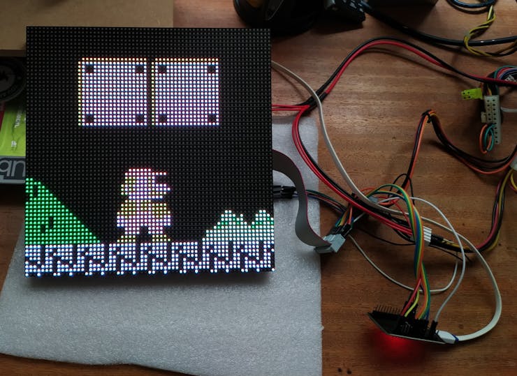
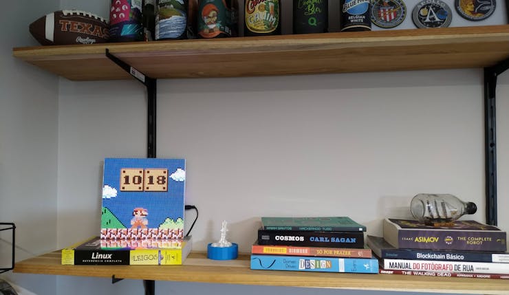
One of the first clockfaces I would like to have was a Mario Bros one, in which he stands on the stage and hits the blocks to change the hours and minutes. I remember seeing and loving this skin in the good times of Pebble watch and always wanted something similar to this. I mean, the idea was so good I'd like to use it somewhere else.
Besides this clockface I built one that displays the time in words, another that shows the time on the world map and another that emulates an analog clock. Besides the appearance of the clock, I would like to add some features, such as: email notification, weather forecast, soccer news, the possibility to send a text message to Clockwise and a myriad of other ideas. But for this article, let's focus on Mario's clock.
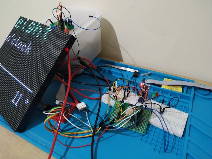
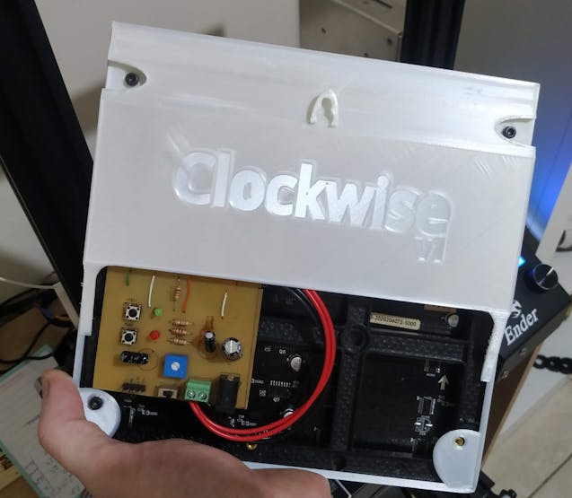
The LED matrix is controlled by an ESP32 and that is what I used in the initial stages of development as shown in the picture above. For those who are interested in creating this project and are not able to create or buy a PCB that will control the display, a simple ESP32 development board will work like a charm and depending on how you organize this bunch of wires it can be a final version too. Just follow the instructions about the wiring on the display driver's GitHub. We are makers, don't be intimidated if you don't have one tool or another, what matters is to get where you want to go.
My own PCB
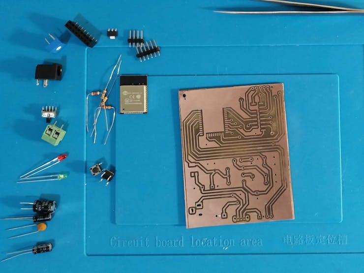

After I made the base code for the clock, I needed a PCB. I really wanted to hang the clock on the wall so I started to prototype my first PCB. I bought a low power laser and adapted it to my 3D printer, so I could design the board that would control the display. This design worked perfectly, although it needs some improvement. You can find it on Github.
Going Pro with the PCB
Tindie has been a great platform where makers from all over the world can create and sell their projects. Brian Lough is one of these guys, I met him on social networks a few years ago and since then he has been working on the ESP32 Trinity a tested and ready-to-use board to control these displays. It couldn't have fit better in this context, all you have to do is plug the board into the display, upload the firmware and voila. Because of this I have retired my PCB that I developed, the Trinity already has everything I need and even more, it even comes with touch sensitive buttons, an LDR (we can regulate the brightness of the display with it), USB-C, power control and much more, you can check more details in the documentation https://github.com/witnessmenow/ESP32-Trinity
Firmware
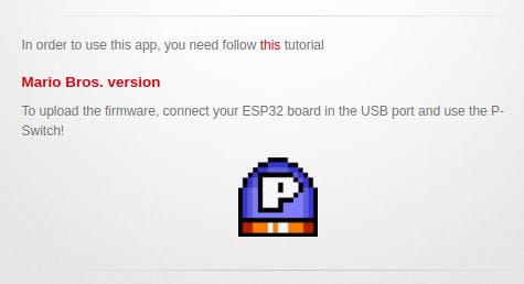
If you don't want to go into the details of how the code works, setup, configuration but just want to see it working, I have good news (thanks Brian for that). You can use the Mario Bros. Clock installer to upload the firmware without having to install anything and without making any effort as it is already compiled. Just plug the ESP32 into the USB port and click the P-Switch to flash. Yes, take me to the installer.
Configuring WiFi
The first time you run it, you need to configure the WiFi, for that connect to the "Clockwise-Wifi" access point with the password 12345678 via your smartphone or laptop, click "Configure WiFi" and select your AP, put in your password and your timezone and save. Then the clock can connect to an NTP server to get the correct time. It is important to use a 2.4GHz WiFi, it will not work on 5G.
About Timezone
WiFi Manager is responsible for collecting the timezone parameter used in the clock to show the time correctly. When instantiating the NTP client, the default time is in UTC, we need to inform the correct timezone during the Wifi setup process. All the available timezone names is listed here, e.g. America/New_York, Asia/Dubai, Europe/Paris, and so on. In my case, I type "America/Sao_Paulo" in the timezone field on WiFi Manager and that's it. If you want to know more about how an NTP server works, I recommend reading this article.
Source Code

I usually use PlatformIO to develop the firmware for my projects. If you don't know it yet, I recommend you to give it a try. But for this article I decided to use the Arduino IDE to make things easier. The code in the repository is ready to work with the ESP32-HUB75-MatrixPanel-I2S-DMA library, but I have also used PxMatrix and everything worked fine. I believe you just need to replace the library without further changes to the code since the base class is the Adafruit_GFX.
To make it work in the Arduino IDE I had to modify a little bit the project structure, all the files went to the root together with mariobros-clock.ino and it can get a little confusing when you see it for the first time. I'll try to organize things here. But before I forget, the source code is available on https://github.com/jnthas/mariobros-clock.
The structure was composed of three folder explained below with the tree of files.
clockface: contains the graphics, font, icons, etc. and the implementation of Mario
commons: contains general utilities such as Date/Time and Wifi configuration
engine: contains implementation used by the display in general, like functions to draw the scenery, sprites, events, etc.
Check the first attached code
With this structure it was possible to assemble the clock that looks like the image attached. Basically we have the scenery with the static objects. We have two sprites, Mario and the blocks. Mario jumps every minute and hits the blocks and the sequence of events is as follows:
Check the second attached code
IDE Setup
Before running it is necessary to install some libraries, all of which can be installed from the Arduino Library Manager.
ESP32-HUB75-MatrixPanel-I2S-DMA: search for "ESP32 HUB75 MATRIX"
Adafruit GFX - search for "Adafruit GFX
FastLED - search for "FastLED"
NTPClient by Fabrice Weinberg - search for "NTPClient".
Adafruit BusIO - just search for the same name
Time by Michael Margolis - search for "timelib".
WiFi Manager by tzapu - search for "wifimanager" all together
ezTime - search for the same name
With all the libraries installed and the correct board selected simply upload it and it should work. After that, follow the instructions provided in Firmware section to configure wifi.
3D Printed Case
To make it easier to hang the clock on the wall, I created a simple case on TinkerCAD. To be honest, 3D modeling is not my strongest skill, but it worked well. Just an advise, this case was modeled thinking in the display I have here at home. I don't know if it will be compatible with all display models, the hole positions may not be the same. I liked the case because it is even easier to manipulate the display.
Next Steps
- Being able to change the clockface via WebSerial API. I would like to create a web app where you could update the firmware by just selecting the clockface you want.
- Create the notification widgets and display them on the watch, they could be configured in the web app itself
- Integrate MQTT into the watch so you can receive these notifications from anywhere
- Create more clockfaces
- The project is open source, if you think you can help me to create more features please feel free to contribute
- Comments about ideas of new clockfaces are welcome
.
├── clockface
│   ├── Clockface.cpp
│   ├── Clockface.h
│   └── gfx
│       ├── assets.h
│       ├── block.cpp
│       ├── block.h
│       ├── mario.cpp
│       ├── mario.h
│       └── Super_Mario_Bros__24pt7b.h
├── commons
│   ├── CWDateTime.cpp
│   ├── CWDateTime.h
│   ├── IClockface.h
│   └── WiFiConnect.h
├── engine
│   ├── EventBus.cpp
│   ├── EventBus.h
│   ├── EventTask.h
│   ├── Game.h
│   ├── Locator.cpp
│   ├── Locator.h
│   ├── Object.h
│   ├── Sprite.cpp
│   ├── Sprite.h
│   └── Tile.h
└── mariobros-clock.ino
1) mario.jump()              // changes the sprite and starts the jump
                             // animation
2) mario.collidesWith(block) // if collision is detected, mario reverses
                             // the movement and starts to fall,
                             // the blocks starts an upward movement
                             // already with the new time set
3) Block reaches the ascent limit and starts to fall until it reaches the starting position.
4) Mario hits the ground and returns to the initial state


