
This Project can Control the City Light System and Monitor the UG Cable Temperature Smartly Over the Internet using Bolt IoT.
Things used in this project
Hardware components
Software apps and online services
Story
STORY/PROBLEM
As it was stated earlier, it is seen in a number of cities that the street light is one of the huge expenses in a city. The cost spent is huge that all the sodium vapor lamps consume more power. The expense spent on the street light can be used for other development of the nation. Currently a manual system is used where the light will be made to switched ON/OFF i.e. the light will be made to switch ON in the evening and switched OFF in the morning. Hence there is a lot of wastage of energy between the ON/OFF. This is one of the major causes of shifting to the automatic system, since there is less wastage of power and thus saving a lot of monetary expenses. Apart from this, the other disadvantages of the existing system are described below.
Underground power transmission cables often have to face the challenge of poor ventilation, which decreases power transmission capacity and damages the materials of the cable in a high temperature environment. It is necessary to take a heat dissipation measure to ensure not only the safety but the efficiency of power transmission systems.
OBJECTIVE
As it was stated earlier, it is seen in a number of cities that the street light is one of the huge expenses in a city. The cost spent is huge that all the sodium vapor lamps consume more power. The expense spent on the street light can be used for other development of the nation. Currently a manual system is used where the light will be made to switched ON/OFF i.e. the light will be made to switch ON in the evening and switched OFF in the morning. Hence there is a lot of wastage of energy between the ON/OFF. This is one of the major causes of shifting to the automatic system, since there is less wastage of power and thus saving a lot of monetary expenses. Apart from this, the other disadvantages of the existing system are described below.
Underground power transmission cables often have to face the challenge of poor ventilation, which decreases power transmission capacity and damages the materials of the cable in a high temperature environment. It is necessary to take a heat dissipation measure to ensure not only the safety but the efficiency of power transmission systems.
PROJECT SCOPE
With the developing country the controlling and monitoring system should be became smart. The light controlling system being online will saves the time. And the condition of the light will make the user to feel safe.
Temperature monitoring system will provide the smart monitoring data to the user. From this the complication of finding the error will be reduces and work will be done effectively.
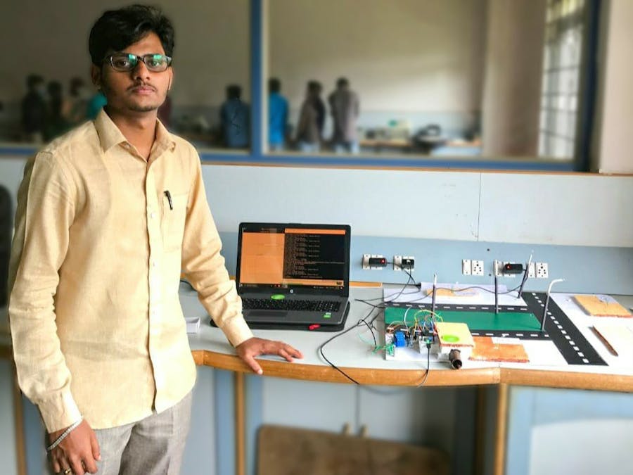
PROJECT KIT
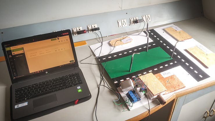
Project Kit : Smart Light City and UG Cable Temperature Monitoring System
BLOCK DIAGRAM
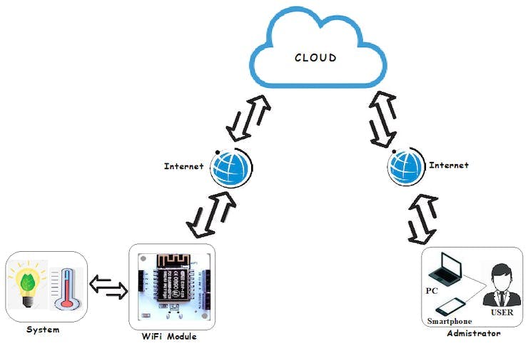
BLOCK DIAGRAM
PIN DIAGRAMS AND CONNECTIONS
1. Light Controlling System
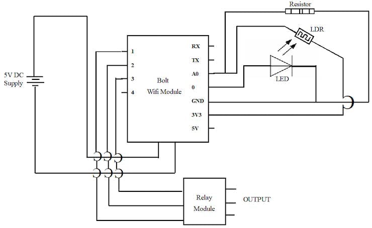
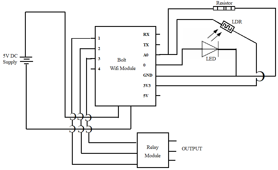
Pin Diagram for Light Controlling System
CONNECTIONS LIGHT CONTROLLING:
Connect Bolt Wi-Fi Module to Power Supply.Do the configuration to make it ONLINE.Make the supply OFF and do the connection as per the pin diagram(Pic05).Connect the LED Between ‘0’ Digital pin and ‘GND’ pin.Connect a Resistor Between ‘A0’ Analogue pin and ‘GND’ pin.Connect the LDR Light Sensor Between ‘A0’ Analogue pin and ‘3V3’ pin.Take the Output from the ‘1’, ’2′, ’3′, Digital pins for Light Connections using 4 channel Relay Module.
2. Temperature Monitoring System.
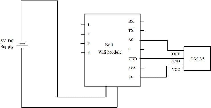
Block Diagram for Temperature Monitoring System
CONNECTIONS FOR TEMPERATURE MONITORS:
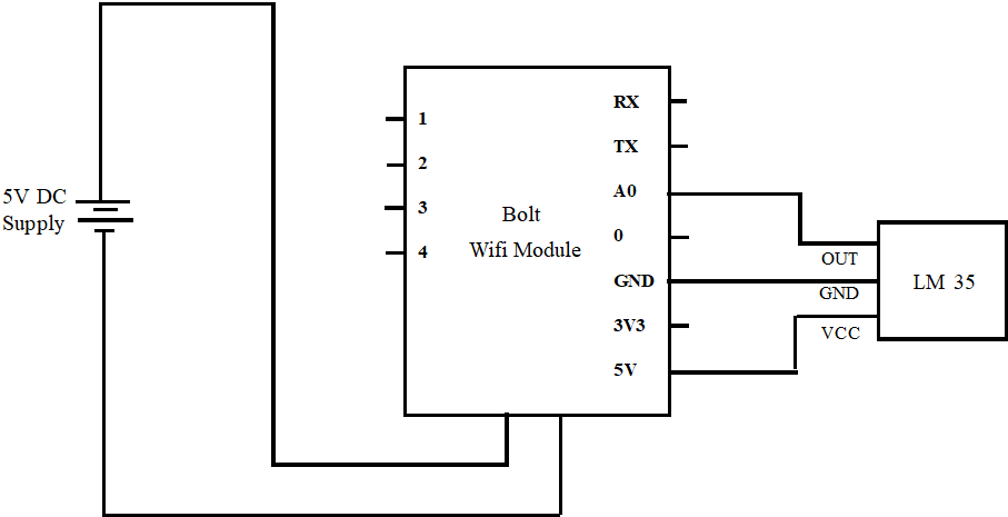
Connect Bolt Wi-Fi Module to Power Supply.Do the configuration to make it ONLINE.Make the supply OFF and do the connection as per the pin diagram(Pic06).Connect the LM35 Temperature Sensor Between ‘A0’ Analogue pin, ‘GND’ pin and ‘5V’ pin.
HARWARE COMPONENTS
Bolt WiFi ModuleLEDLight SensorTemperature SensorResistorJumper WiresBread-BoardAndroid or IOS MobileComputer or LaptopPower Supply
SOFTWARE CONTENTS
Bolt CloudBolt IoT AppHTMLJava ScriptPythonLinuxUbuntuOracle Virtual Box
PRESENT WORK/ METHODOLOGY
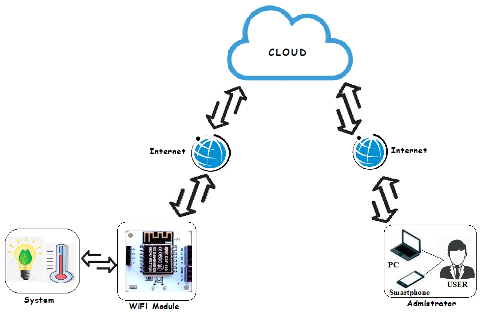
In this project Bolt IoT module is used for the controlling the light system and the temperature monitoring of the underground cables. To make the easy and convenient process of using the Bolt IoT module, the Bolt provided their own application, own cloud interface, own Devices for the user. The application name as “Bolt IoT App”, the cloud named “https://cloud.boltiot.com [https://cloud.boltiot.xn--com-9o0a/]” and the devices names as “Bolt Wi-Fi Module”. The maximum 5v supply is given to the Bolt module. The circuit is made connected as per the connection method and the device is connected to the Bolt Cloud through internet using the interfacing devices which in Android or IOS Mobile. Through the Cloud the required program and instructions will be inserted to the Bolt Wi-Fi Module device, then the device works as per the requirement, without any physical connections between the Cloud and the Device.
Light Controlling project is connecting the light system to the Bolt Cloud using the Bolt IoT module. In the Bolt Cloud, through user interface we are operating the ON/OFF system of the light. The respected HTML program will be inserted to the Bolt Wifi Module from the cloud interface to control the ON/OFF condition of the light. The Python program will interface to the Bolt device through the Linux Ubuntu 16.04 Terminal box, which sends the alert massage to the user about the live condition of the device. As per the algorithms given in the program the device works or talk with the Bolt IoT Cloud. The user can control the light system from the Cloud interface and the Bolt App.
Temperature monitoring project is sensing the live temperature of the underground cables. The sensor LM 35 is used in this project for the live temperature sensing. The sensor is placed at the point where the underground cables are laid. The sensor is activated by the Bolt IoT wifi module, this module is interfaced to the Bolt cloud. The Java Script program is inserted to the Bolt Wifi Module through cloud interface to get the live temperature in Cloud interface. The Python program will interface to the Bolt device through the Linux Ubuntu 16.04 Terminal box, which sends the alert massage to the user whenever the temperature exceeds the minimum or maximum limit of the temperature which in set in the program. The user can monitor the live temperature on Cloud interface and at the Bolt App.
SOFTWARE PROGRAMMING
SOFTWARE PROGRAMMING
1. LIGHT CONTROLLING
two parts
a. confy.py [http://a.confy/]
SID = "ACbd37ff2f1db29bc0c0xxxxxx3666b5"
AUTH_TOKEN = "f15ee60f368502bxxxxxx6f21bec"
FROM_NUMBER = "+19048XXX11"
TO_NUMBER = "+91782XXXXX02"
API_KEY = "c31407d6-51db-4435-xxxx-8e8xxxxx511"
DEVICE_ID = "BOLT1316XXXX"
b. light_sms.py
import conf, json, time, math, statistics
from boltiot import Sms, Bolt
def compute_bounds(history_data,frame_size,factor):
     if len(history_data)<frame_size:
         return None
     if len(history_data)>frame_size:
         del history_data[0:len(history_data)-frame_size]
     Mn=statistics.mean(history_data)
     Variance=0
     for data in history_data :
         Variance += math.pow((data-Mn),2)
     Zn = factor*math.sqrt(Variance/frame_size)
     High_bound=history_data[frame_size-1]+Zn
     Low_bound=history_data[frame_size-1]-Zn
     return[High_bound, Low_bound]

mybolt = Bolt(conf.API_KEY,conf.DEVICE_ID)
sms=Sms(conf.SSID, conf.AUTH_TOKEN, conf.TO_WHATSAPP, conf.FROM_WHATSAPP)
history_data=[]

while True:
     response =mybolt.analogRead('A0')
     response1 =mubolt.analogRead('A0')
     data= json.loads(response)
     if data['success']!=1
         print("There was an Error while retriving the data.")
         print("This is the Error:"+data['value'])
         time.sleep(10)
         contiue

     print("This is the value"+data['value']
     sensor_value=0
     try:
         sensor_value = int(data['value'])
     except e:
         print("There was an error while parsing the response:",e)
         continue

     bond = compute_bounds(history_data, conf.FRAME_SIZE, conf.MUL_FACTOR)
     if not bound:
         required_data_count = conf.FRAME_SIZE-len(history_data)
         print("Not enough data to compute Z-core. Need", required_data_count,"more data points")
         history_data.append(int(data['value']))
         time.sleep(10)
         continue

     try:
         if sensor_value > bound[0]:
              print("The light level increased suddenly. Sending an SMS.")
              response = sms.send_sms("The lights are turned ON")
              response1 = sms_whatsapp.send_sms("The Lights are Turned ON")
              print("This is the response for sms", response)
              print("This is the response for whatsapp", response1)
         elif sensor_value<bound[1]:
              print("The light level decreased suddenly. Sending an SMS.")
              response = sms.send_sms("The lights are turned OFF")
              response1 = sms_whatsapp.send_sms("The Lights are Turned OFF")
              print("This is the response for sms", response)
              print("This is the response for whatsapp", response1)
         history_data.append(sensor_value);
     except Ecxeption as e:
         print("Error",e)
     time.sleep(10)
1. TEMPERATURE MONITORING
two parts
a. confy.py: http://a.confy/
SID = "ACbd37ff2f1db29bc0c08xxxx83666b5"
AUTH_TOKEN = "f15ee60f368502bxxxxxx76f21bec"
FROM_NUMBER = "+19048XXXX1"
TO_NUMBER = "+91782XXXXX202"
FROM_WHATSAPP = "whatsapp: +141552XXXX6"
TO-WHATSAPP = "whatsapp: +917829XXXX2"
API_KEY = "c31407d6-51db-4435-xxxx-8e8acXXXXX11"
DEVICE_ID = "BOLT131XXXXX"
FRAME_SIZE= 3
MUL_FACTOR = 10
b. temprature_sms
import conf
from boltiot import Sms, Bolt
import json, time

minimum_limit = 32
maximum_limit = 37

mybot = Bolt(conf.API_KEY, conf.DEVICE_ID)
sms = Sms(conf.SSID, conf.AUTH_TOKEN, conf.TO_NUMBER, conf.FROM_NUMBER)

while True:
     print("Reading sensor value")
     response = mybolt.analogRead('A0')
     data = json.loads(response)
     print("Sensor value is: " +str(data['value']))
     try:
         sensor_value = int(data['value'])
         Temprature = (100*sensor_value)/1024
         print("The Current Temprature is : ",Temprature)
         if Temprature > maximum_limit of Temprature < minimum_limit:
              print(" Making Request to Twilio to send a SMS")
              response = sms.send_sms("ALERT: Your underground cable tempratre is not in expected limit, The current temprature sensor value is" +str(Temprature))
              print("Response recieved from Twilio is: " +str(response))
              print("Status of the SMS at Twilio is:" +str(response.status))
     except Exception as e:
         print("Error occured : Below are thw details")
         print(e)
     time.sleep(10)
PROJECT BENEFITS
Automatic switching of street lightsMaintenance cost reductionReduction in CO₂ emissionReduction of light pollutionWireless communicationWireless monitoringEnergy savingReduction of manpower
CONCLUSION AND FUTURE SCOPE
A design scheme for controlling a streetlight based on Bolt Wi-Fi module has been demonstrated, which can be programmed to react to events (based on day and night detection) and to cause corresponding actions. The proposed scheme provided with the mode in which automated system is used to control the streetlights. i.e based on light intensity the sensor sends the data to bolt and it till take actions according to the algorithm
IoT based temperature and humidity detecting device provides an efficient and definitive system for monitoring agricultural parameters. The system also provides a corrective movement or decision-making system. IoT based monitoring of area is a handiest, but it also allows the consumers to research the correct modifications within the surroundings and for taking possible action. It is inexpensive and consumes much less electricity
IoT based system can be extended for controlling extraordinary electronic and electric devices from remote locations.
Project Links
1. To view about the project on Bolt IoT portal go through the following link
http://projectsubmission.boltiot.com/?p=17848
2. To watch working of the project on YouTube go through this following link
Schematics
BLOCK DIAGRAM OF PROJECT
Block Diagram of the Project
PIN Diagram for Light Controlling
Pin Diagram for Light Controlling Project
PIN Diagram for Temperature Monitoring
Pin Diagram For Temperature Monitoring
Code
Conf_light
Python
Configuration file for Light Controlling
SID = "ACbd37ff2f1db29bc0c08faff2383666b5"
AUTH_TOKEN = "f15ee60f368502b2b82ce0e776f21bec"
FROM_NUMBER = "+19048440611"
TO_NUMBER = "+917829136202"
API_KEY = "c31407d6-51db-4435-ba78-8e8ac9eda511"
DEVICE_ID = "BOLT13167236"
Light_sms.py
Python
Program for light controlling Working
import conf, json, time, math, statistics
from boltiot import Sms, Bolt
def compute_bounds(history_data,frame_size,factor):
     if len(history_data)<frame_size:
         return None
     if len(history_data)>frame_size:
         del history_data[0:len(history_data)-frame_size]
     Mn=statistics.mean(history_data)
     Variance=0
     for data in history_data :
         Variance += math.pow((data-Mn),2)
     Zn = factor*math.sqrt(Variance/frame_size)
     High_bound=history_data[frame_size-1]+Zn
     Low_bound=history_data[frame_size-1]-Zn
     return[High_bound, Low_bound]

mybolt = Bolt(conf.API_KEY,conf.DEVICE_ID)
sms=Sms(conf.SSID, conf.AUTH_TOKEN, conf.TO_WHATSAPP, conf.FROM_WHATSAPP)
history_data=[]

while True:
     response =mybolt.analogRead('A0')
     response1 =mubolt.analogRead('A0')
     data= json.loads(response)
     if data['success']!=1
         print("There was an Error while retriving the data.")
         print("This is the Error:"+data['value'])
         time.sleep(10)
         contiue

     print("This is the value"+data['value']
     sensor_value=0
     try:
         sensor_value = int(data['value'])
     except e:
         print("There was an error while parsing the response:",e)
         continue

     bond = compute_bounds(history_data, conf.FRAME_SIZE, conf.MUL_FACTOR)
     if not bound:
         required_data_count = conf.FRAME_SIZE-len(history_data)
         print("Not enough data to compute Z-core. Need", required_data_count,"more data points")
         history_data.append(int(data['value']))
         time.sleep(10)
         continue

     try:
         if sensor_value > bound[0]:
              print("The light level increased suddenly. Sending an SMS.")
              response = sms.send_sms("The lights are turned ON")
              response1 = sms_whatsapp.send_sms("The Lights are Turned ON")
              print("This is the response for sms", response)
              print("This is the response for whatsapp", response1)
         elif sensor_value<bound[1]:
              print("The light level decreased suddenly. Sending an SMS.")
              response = sms.send_sms("The lights are turned OFF")
              response1 = sms_whatsapp.send_sms("The Lights are Turned OFF")
              print("This is the response for sms", response)
              print("This is the response for whatsapp", response1)
         history_data.append(sensor_value);
     except Ecxeption as e:
         print("Error",e)
     time.sleep(10)
Conf_temp
Python
Configuration file for Temperature Monitoring
SID = "ACbd37ff2f1db29bc0c08faff2383666b5"
AUTH_TOKEN = "f15ee60f368502b2b82ce0e776f21bec"
FROM_NUMBER = "+19048440611"
TO_NUMBER = "+917829136202"
FROM_WHATSAPP = "whatsapp: +14155238886"
TO-WHATSAPP = "whatsapp: +917829136202"
API_KEY = "c31407d6-51db-4435-ba78-8e8ac9eda511"
DEVICE_ID = "BOLT13167236"
FRAME_SIZE= 3
MUL_FACTOR = 10
Temperature_Sms
Python
Program for Working of Temperature Monitoring
import conf
from boltiot import Sms, Bolt
import json, time

minimum_limit = 32
maximum_limit = 37

mybot = Bolt(conf.API_KEY, conf.DEVICE_ID)
sms = Sms(conf.SSID, conf.AUTH_TOKEN, conf.TO_NUMBER, conf.FROM_NUMBER)

while True:
     print("Reading sensor value")
     response = mybolt.analogRead('A0')
     data = json.loads(response)
     print("Sensor value is: " +str(data['value']))
     try:
         sensor_value = int(data['value'])
         Temprature = (100*sensor_value)/1024
         print("The Current Temprature is : ",Temprature)
         if Temprature > maximum_limit of Temprature < minimum_limit:
              print(" Making Request to Twilio to send a SMS")
              response = sms.send_sms("ALERT: Your underground cable tempratre is not in expected limit, The current temprature sensor value is" +str(Temprature))
              print("Response recieved from Twilio is: " +str(response))
              print("Status of the SMS at Twilio is:" +str(response.status))
     except Exception as e:
         print("Error occured : Below are thw details")
         print(e)
     time.sleep(10)
The article was first published in hackster, September 9, 2022
cr: https://www.hackster.io/kykhaveri/smart-light-city-ug-cable-temperature-monitoring-system-8204f8
author: Khudabaksh•yk _6


