
Hi There,
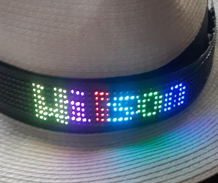
Recently, I finished up on my DIY project Wilson: the IoT hat. Because of the big fun I had creating and using this IoT hat, and given the wonderful feedback it provided to the wearer, I really want to share this project with you.
Wilson is a hat equipped with a multicolor LED matrix and some electronics. It comes with a smartphone app to control it. Thus you can show different messages in different styles by using your own phone. You can also program Wilson to display incoming Text messages.
To prevent abuse (you don’t want to send out nasty messages) a blacklist function is present, and an auto-reply function is available (and lot’s of fun).
This Instructable aims to provide all necessary instructions, resources and knowledge for you to create you own IoT hat.
It’s easy to build. The Arduino (Hat) programming is straight-forward. The accompanying Android App (to process incoming SMS messages) is slightly more difficult. However I will try to explain my code to you in this instructable.
Here we go.
Step 1: Building the Hat-tech
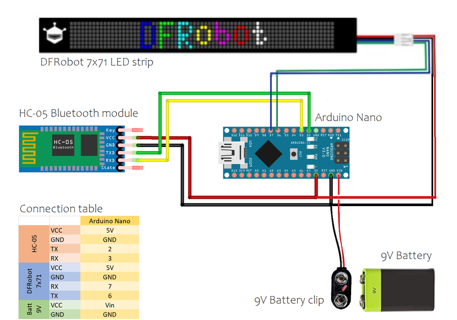
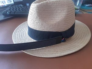

Fist, we need to wire-up all components for the hat to combine them into the hat assembly.
The Led-strip can be glued to the front of the hat. Using a Hat with a black (slightly broader) ribbon hides the Led-strip from sight when no messages are displayed. You will have to punch a hole in the side of the hat to allow for the wires of the Led-strip to go through, and get attached to the inside of the hat.
Then solder the HC-05 bluetooth module, the Led-strip and battery-clip to the Arduino using the following schematics.
Please make sure to make sturdy connections when soldering and wrap all components firmly into shrink sleeves. Then attach the battery, Arduino and Bluetooth module to the inside of the hat.
Hiding the battery within the hat in a way that it is of no nuisance to the wearer can be difficult because of the weight of the battery. I found the best way to be with some Velcro strips glued to the inside of the hat containing the battery.
You can optionally equip your hat with a power-switch. You will save on batteries that way.
Step 2: Pairing With the Hat
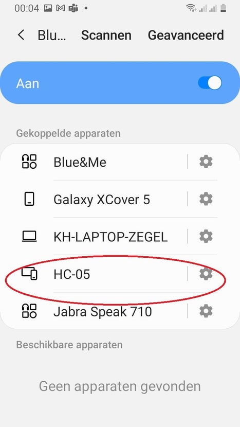
Now, when powered-on and wired correctly, the hat assembly will be Bluetooth discoverable. Even if no software is loaded on the Arduino. The hat assembly will be discoverable using the name HC-05 and uses the password 0000 or 1234 for pairing.
Then, please pair your Android smartphone with the hat assembly.
Step 3: Setting Up the Arduino IDE & Installing Arduino Libraries
Setting-up the IDE
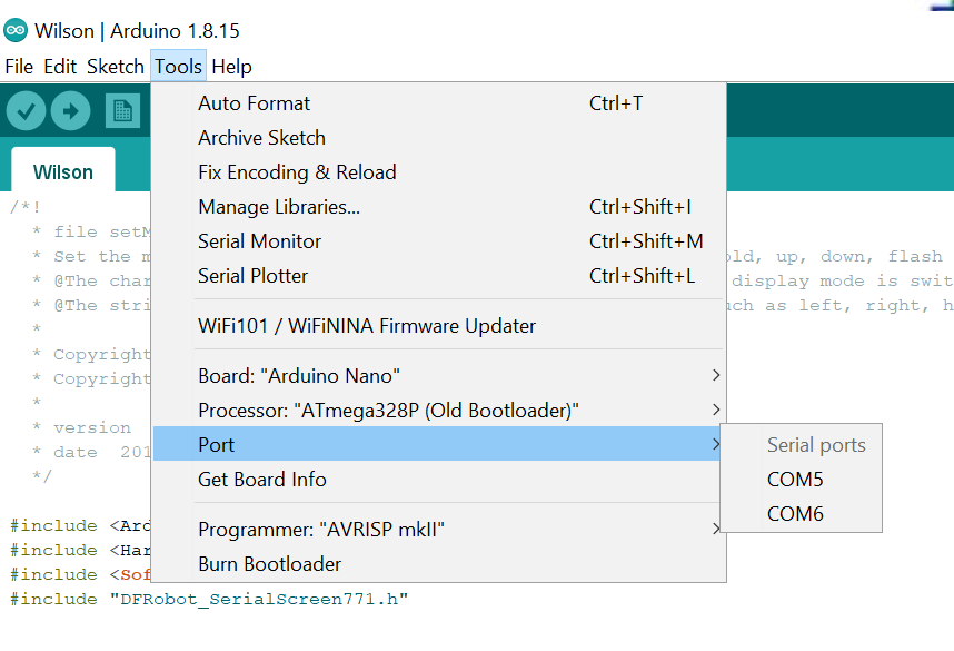
The hat runs on an Arduino Nano and we will be using the Arduino IDE to create a sketch (program) and upload this program to the Arduino using a USB cable. After installation of the Arduino IDE and accompanying USB drivers, you have to connect the Arduino and PC through a USB cable and select -within the Arduino IDE- the correct serial port used by this USB connection.
When identified and selected the right port (you can check which port it is through the Windows devicemanager), please then select the right board and processor within the Arduino IDE as shown herein figure 5.
If clicking on Get Board Info (within the Tools menu as shown here) results in a valid response from the Arduino, you’re ready to go to the next step: installing the libraries.
Installing Arduino libraries.
Our Arduino is wired to two external components. 1) the Led-strip and 2) the Bluetooth module. In order to access these components from our own Arduino code, we need 2 helper files. One for both of them.
Luckily, the helper files for Bluetooth are already installed within the IDE .
The DFRobot helper files for the Led-strip need to be downloaded from the DFRobot website here, and then the downloaded package needs to be installed within the Arduino IDE. Please consult this page if you are not sure on how to install such libraries.
On the Arduino side…all preparation work is now done. So before proceeding to the next step, it can be very helpful to verify the correct assembly of hardware and software at this stage.
We can verify if the software-components softwareserial (for Bluetooth) and dfrobot_serialscreen771 (for Led-strip) have been installed correctly within the Arduino IDE by checking if the accompanying examples are available in the IDE. If so…the components itself should be available as well.
Step 4: Testing Arduino Hard- and Software
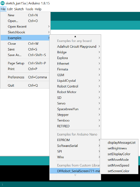
Before writing our own code, we now can test our assembly using the examples provided by the manufacturers. Please test the operation of the Led-strip by uploading one of the example files supplied by DFRobot to your Arduino and check the display accordingly. These example-files were installed while installing the helper files and are available from the Arduino IDE menu at [Files] [Examples] [DFRobotSerialscreen_771-master]. Please make sure you use correct RX and TX port values (6 and 7) in the file you use.
Then test the Bluetooth module. There are many examples available.
When you have verified correct operations of the individual components of the hat assembly, you are ready to create a new hat-application from your brain and write some code for it. To do so, start a new sketch within the Arduino IDE and give this sketch a name. I’ve named the sketch that we will be using in this Instructable ‘Wilson’. You can name yours Steve if you like.
Step 5: Writing Arduino Code & Testing
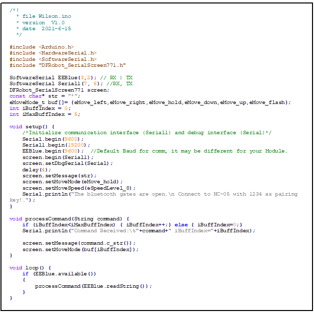
The included file Wilson.ino provides a simple, working example for a IoT hat.
To use it, please copy and paste the text from the included file arduino-code.txt into the Arduino code file you’ve just created. Or load the attached file Wilson.ino into the Arduino IDE.
Then save and upload the file to the Arduino.
If all is right, this file will now be running on the Arduino, a sliding asterix will be shown on the Led-strip and the Bluetooth module will be flashing.
Later-on we will be creating our own Android app to control this hat assembly but for now, we can test the assembly and Bluetooth operations by using a 3rd party app from your smartphone.
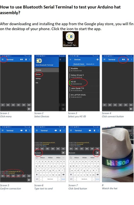
Now, to control your hat and your Arduino assembly without creating your own Android app you can download this app on your Android smartphone. You can also use any other app that can make a serial connection over Bluetooth and send text through it.
If you use the suggested app you first need to connect to the already paired HC-05 device by clicking the menu-icon on the upper-left of the starting page and then selecting Devices from the menu . From the Devices page select the HC-05 device and you will be returned to the starting page of the application where you can start the connection by clicking the connect button .
If everything is OK, a connection over Bluetooth will be established between the hat and your Android smartphone. The Serial Bluetooth Terminal app will confirm an established connection in the main terminal window . Then you can type your own message to display on your hat.
Step 6: Creating an Android App to Control Wilson
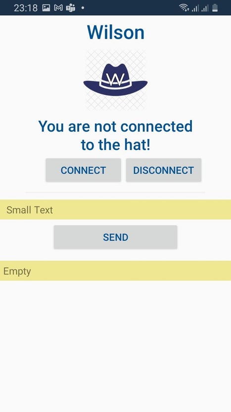
Last step is to create a smartphone app that communicaties -over Bluetooth- with the Arduino assembly.
Included in this instructable is a Visual Studio solution where a Xamarin project template was used to create an Android app. When deployed to your phone and after setting the right permissions, your hat will display incoming SMS messages.
Hope you will enjoy this as much as I do.
The article was first published in INSTRUCTABLES JUNE 17, 2021
cr: https://www.instructables.com/Wilson-the-IoT-Hat/
author: OlivierZ


