

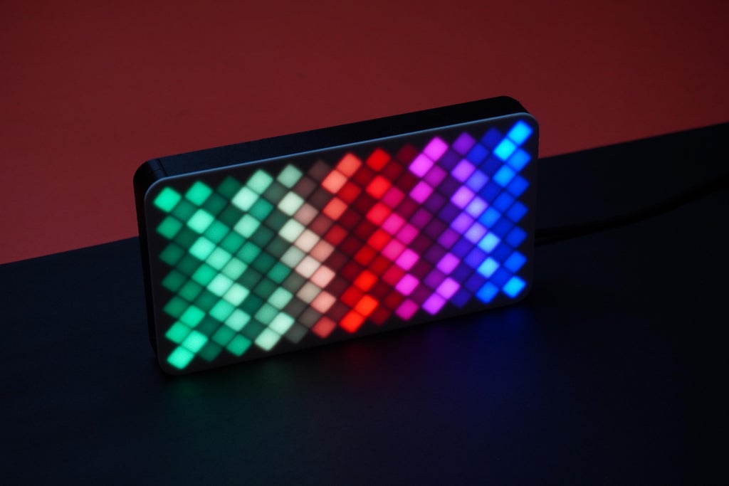
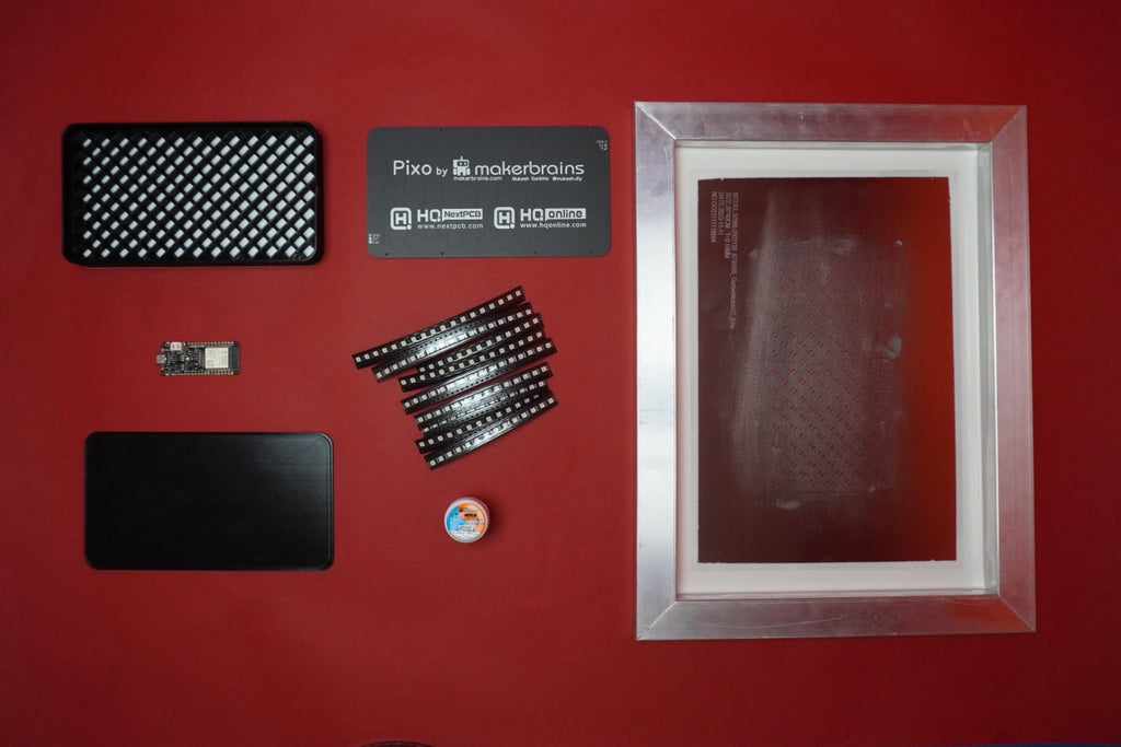
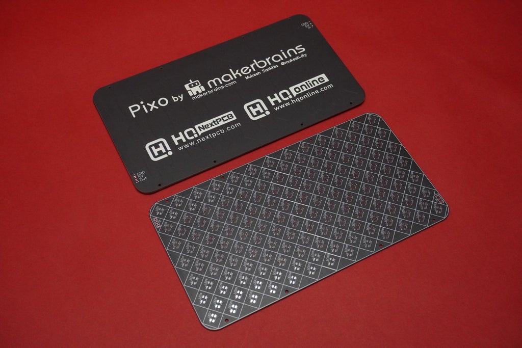
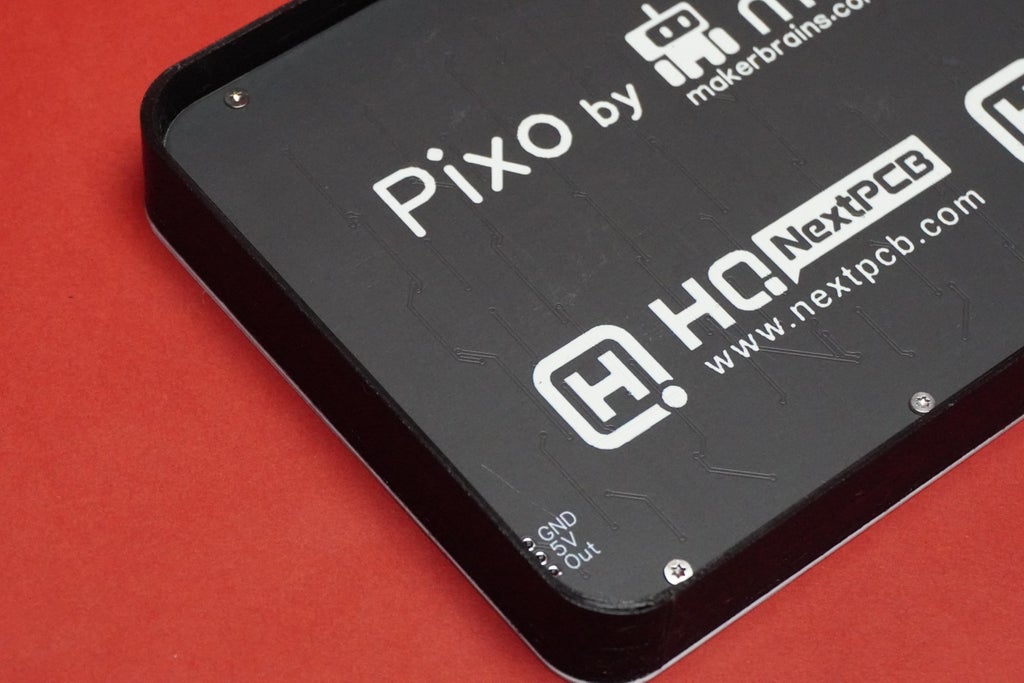
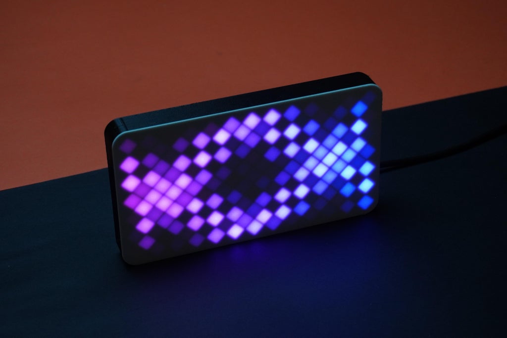
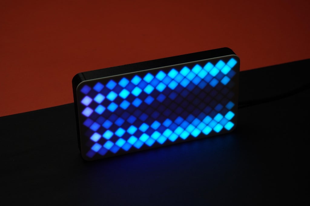
Introducing Pixo, a stunning RGB LED desk matrix that brings mesmerizing rainbow patterns to life! Crafted with a custom-designed PCB, 3D printed components, and powered by an ESP32, Pixo features 163 WS2812B Mini LEDs for a vibrant and enchanting display. Transform your workspace with Pixo's colorful charm and dynamic lighting experience.

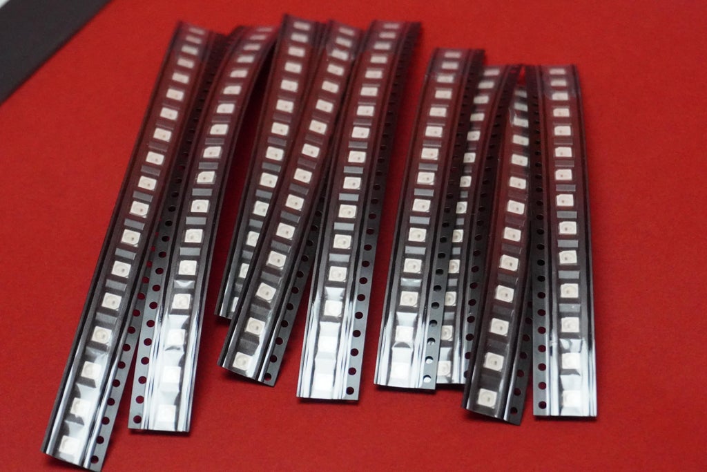
The WS2812B Mini is a type of programmable LED that works in a simple and fascinating way. Each tiny LED has a built-in microcontroller, allowing it to be individually controlled. It's like having a little smart light on its own!
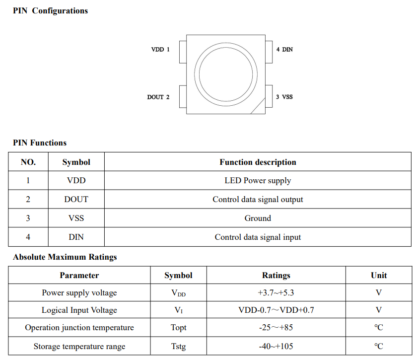
Here's the magic: You can send signals to these LEDs using a device like an ESP32. These signals tell each LED what color to shine, how bright, and when to change. This is possible because of the "OneWire" communication protocol, a simple serial protocol that lets you control multiple WS2812B LEDs in a chain using a single data line. This protocol ensures that each LED interprets the relevant data for its color and brightness accurately. With this technology, you can create all sorts of beautiful and dynamic lighting effects, including the mesmerizing rainbow patterns in the Pixo project.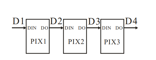
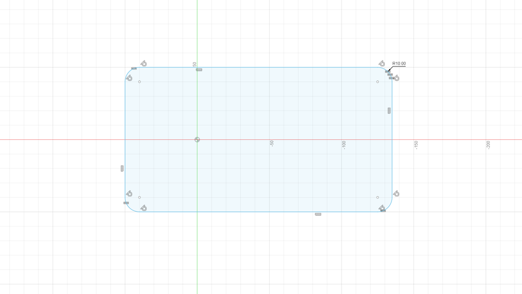
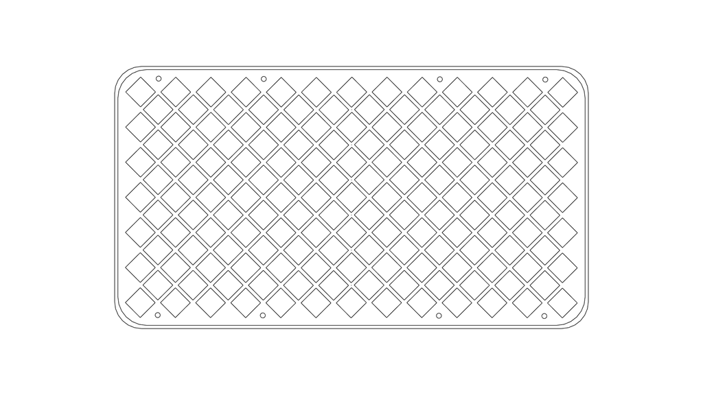
I started by creating the shapes for the LED arrangement using Fusion 360. I also designed the outer border of the matrix and saved them as DXF files.
You can find and download the DXF files from below that I created for your reference.
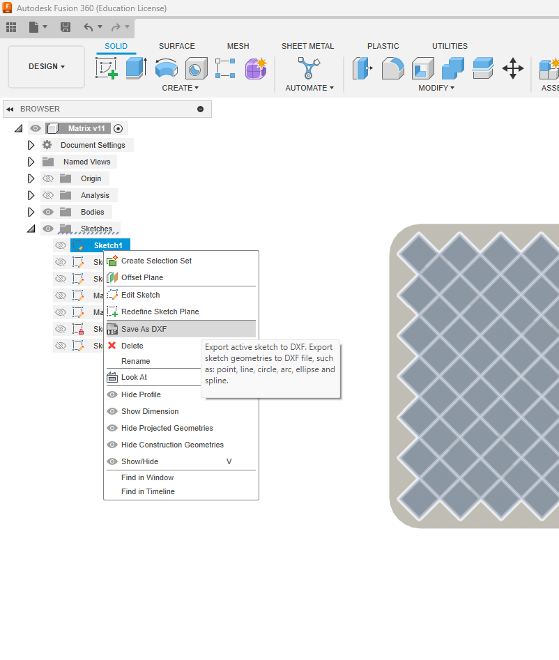
After that, I imported these DXF files into EasyEDA, which is the software I used for designing the PCB. This helped me reference the shapes accurately during PCB designing process.
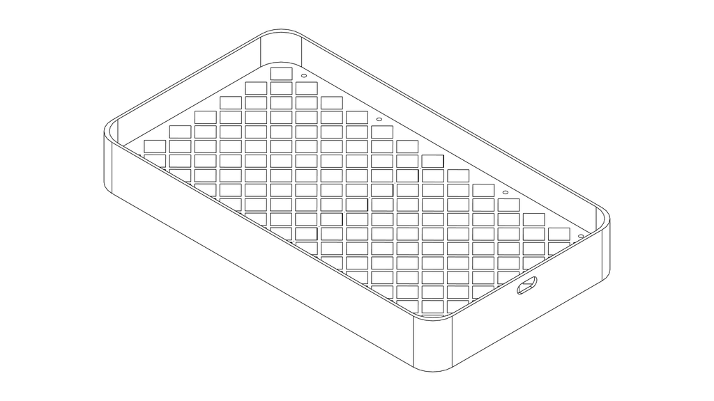
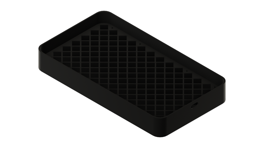
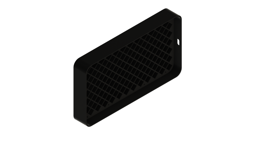
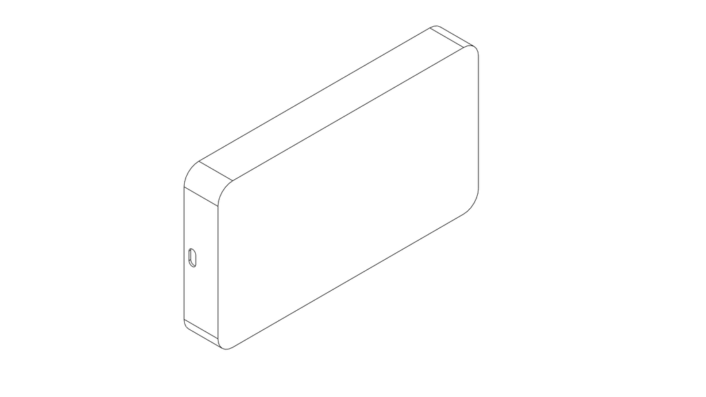
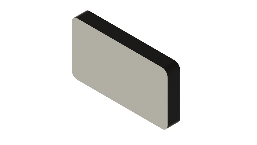
Using the fundamental tools in Fusion 360, I crafted the enclosure and cover for the LED matrix. If you want to learn basics of Fusion 360 you can have a look at my previous article that explains the Fusion 360 fundamentals.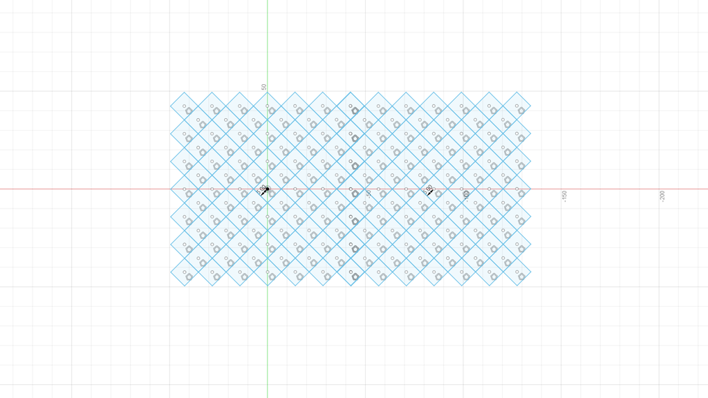
In these steps, I imported the DXF files and used them to design the PCB. If you're new to PCB design, you can check out this helpful tutorial: Tutorial Link.
Once I completed the design, I generated Gerber files. These files are essential for getting the PCB fabricated. You can directly download the Gerber file and order your own PCBs.


Reflow soldering is like baking cookies but with electronic components on a circuit board. Here's how it works:
Apply Solder Paste: Imagine your circuit board is like a cookie dough sheet. You squeeze tiny amounts of solder paste (like putting chocolate chips on cookie dough) on the spots where the electronic parts will go.Place Components: Now, you put the electronic components, like resistors and chips, on their designated spots. These components stick to the solder paste.Preheat: Just as you preheat an oven for cookies, the whole board is preheated to make everything warm and cozy.Reflow: Now, it's time to heat things up even more. This is when the board goes into an oven-like machine. The solder paste melts, creating a deliciously gooey connection between the components and the board.Cool Down: After the "melting" step, the board cools down. The melted solder hardens, securing the components in place. It's like your cookies cooling and becoming solid.And there you have it! Your circuit board is now all set, and the components are nicely soldered, creating a functional electronic treat.
But here's the surprising part: I didn't have a Reflow Station, so I used a regular clothes iron. Yes, you read that right—a clothes iron to melt the solder paste. I came across this method online, saw others trying it successfully, and decided to give it a shot. Surprisingly, it worked quite well! If you're up for saving some money, you might want to give it a try too ;). Just be cautious and take all necessary precautions to avoid accidents or risks.
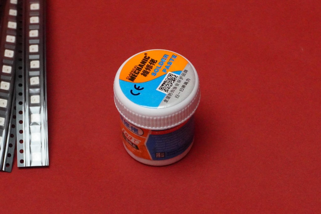
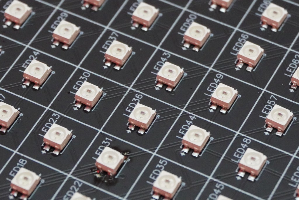
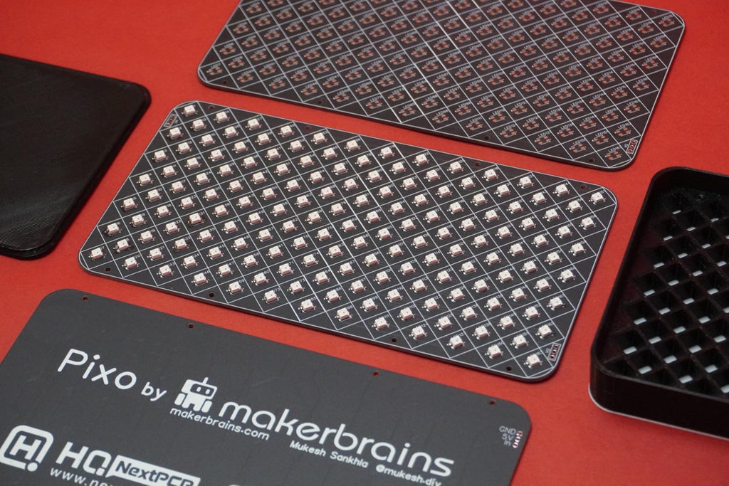
To solder the LEDs, I used a special solder paste that melts at temperatures between 180-190 degrees. First, I set up the PCB and created a temporary fixture using a few old PCBs and masking tape. Then, I placed the stencil that I ordered along with the PCB to apply the solder paste evenly. Using double-sided tape, I secured the stencil on top of the PCB and applied the paste.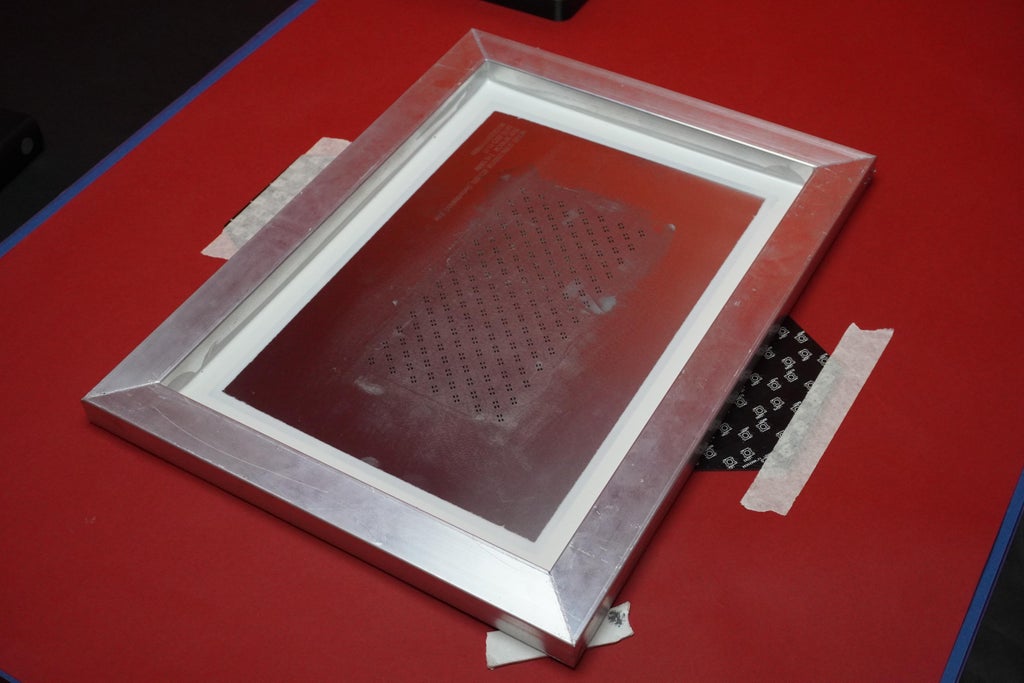
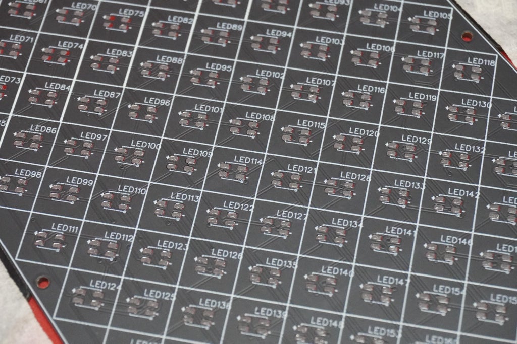
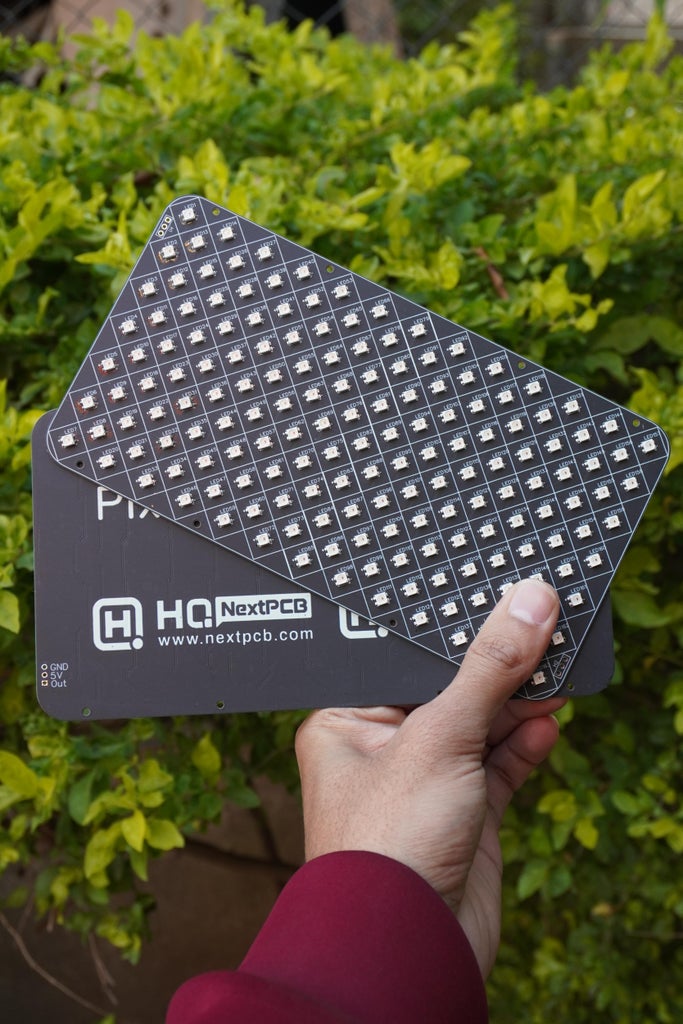
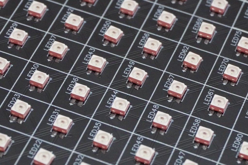
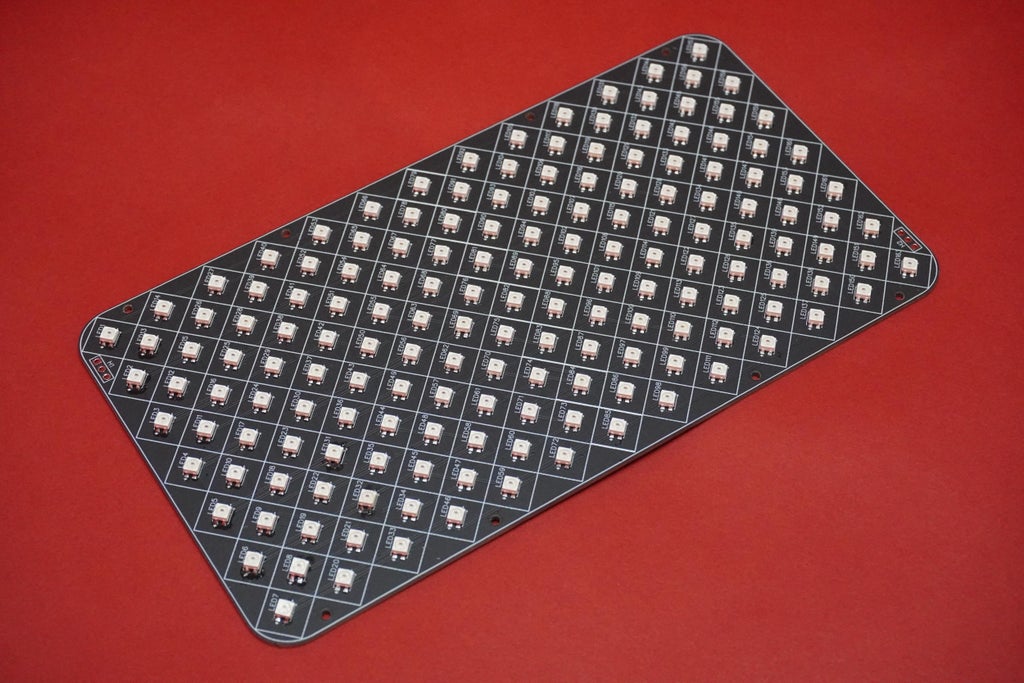
After applying the paste, I carefully positioned all 163 individual LEDs, making sure the LED notch is aligned at the negative (-) side.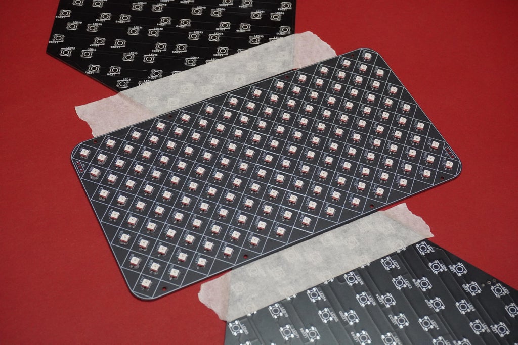
Once all the LEDs were in place, I gently lifted the PCB and put it on the preheated clothes iron.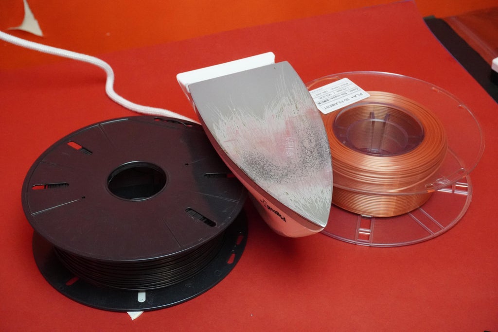
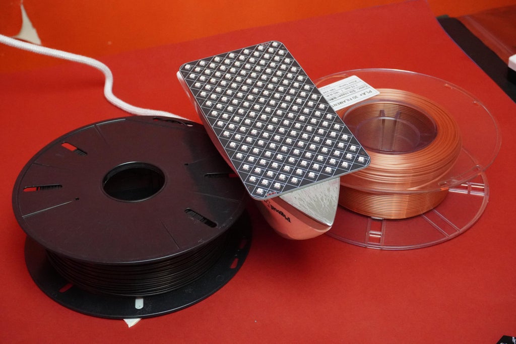
Carefully move the PCB around and check to see the solder paste melt and the LED soldering process happening.
Once done, remove the PCB from the iron and let it cool.
Now, test the Pixo using the provided code. If you find any LED not working, use a soldering gun to make sure the LED is properly aligned and soldered. This should fix the issue. If not, try replacing the LED using a rework station.
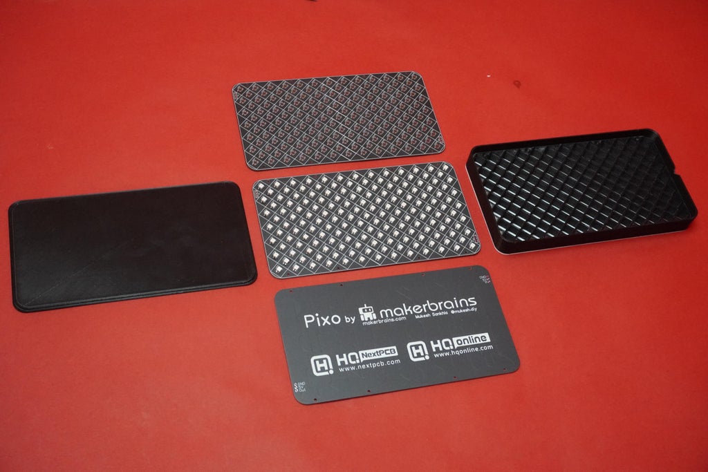
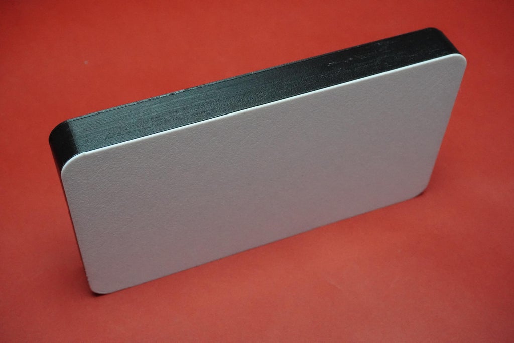
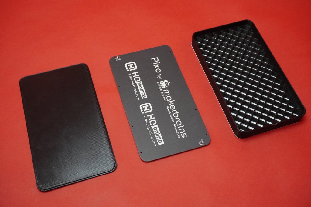
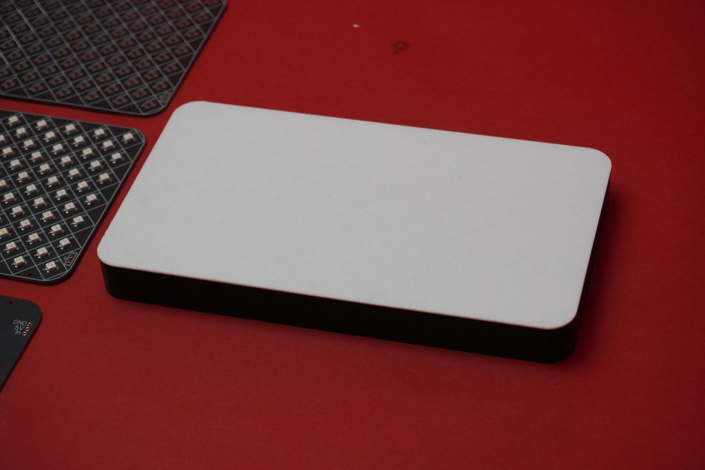
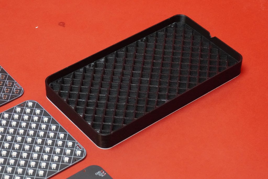
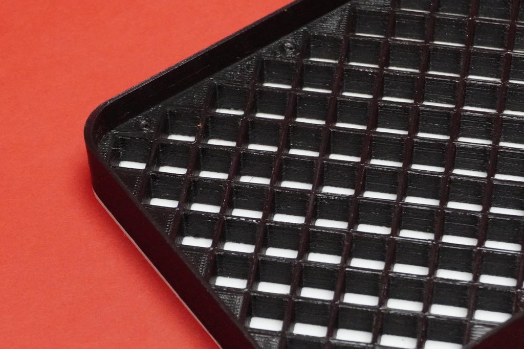
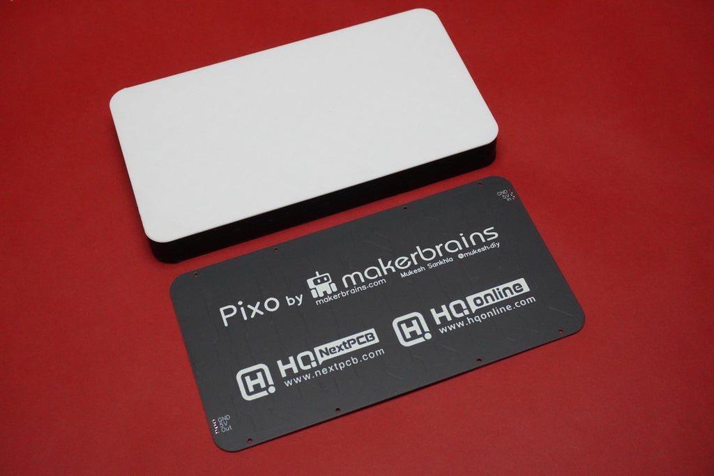
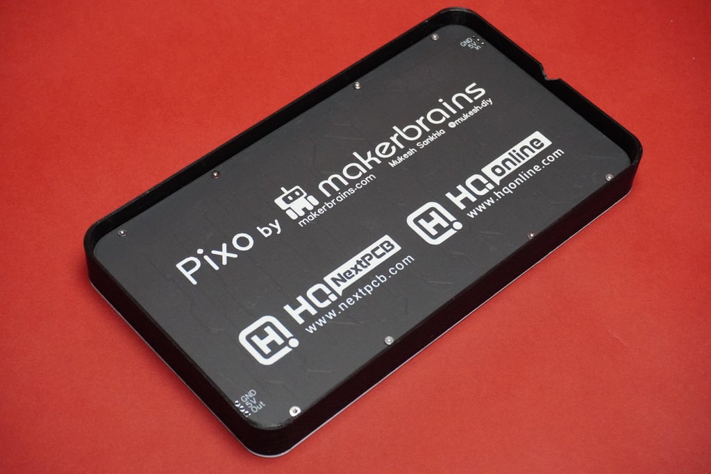
Now, I've got the Pixo enclosure and back cover 3D-printed, both of which I designed. I utilized the Anycubic Neo 3D printer with a 2mm layer height.
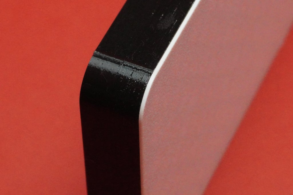
Take note: in my design, the enclosure and diffuser are part of the same body, allowing for a seamless one-body print. To achieve this, start 3D printing from the flat (diffuser) side using white filament. Don't forget to change the filament as soon as the printer reaches the array walls.
Feel free to download the STL files and get started with your 3D printing.
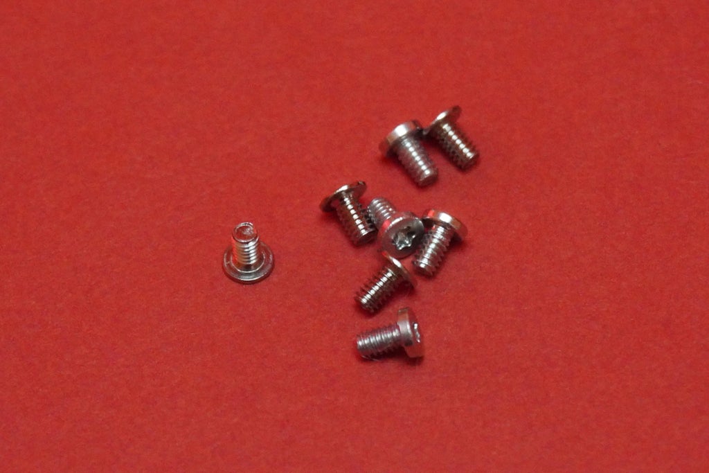
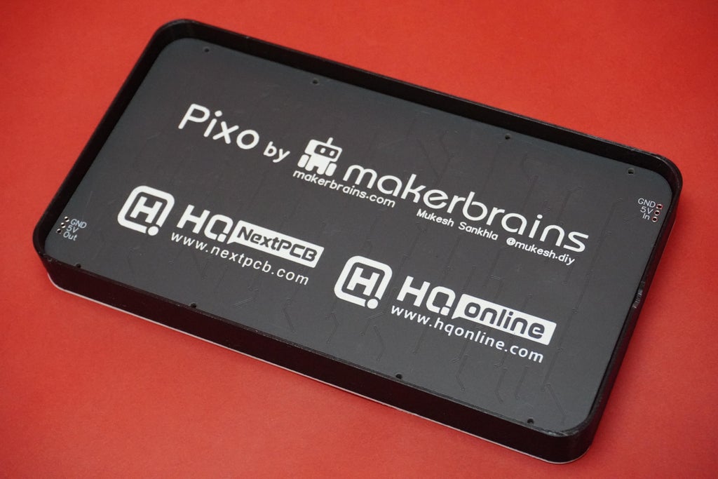
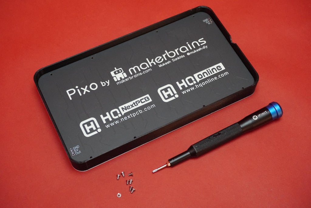
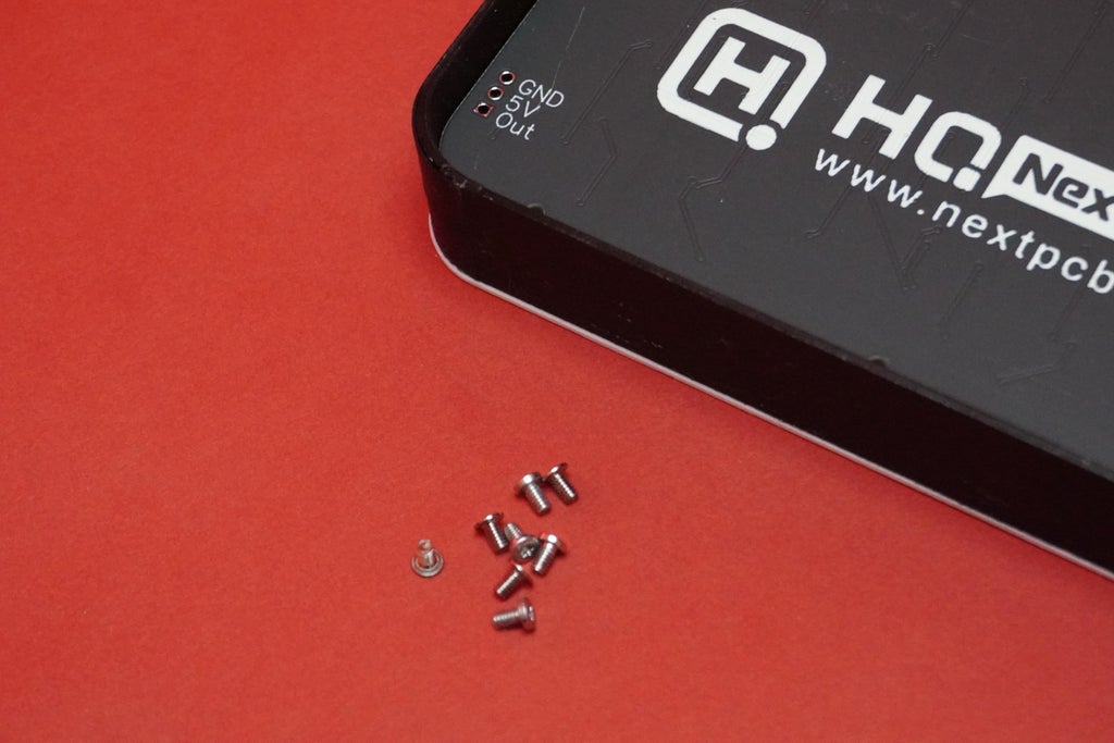
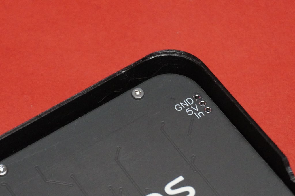
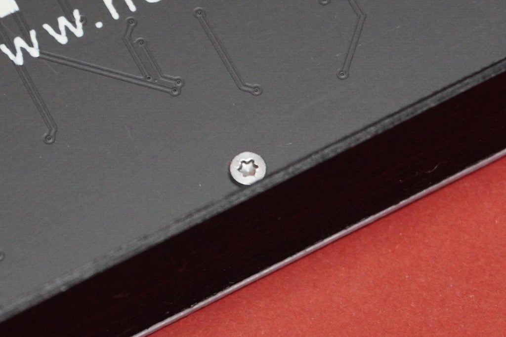
For the assembly process, take the 3D printed housing, position the PCB, align the holes, and secure the PCB to the housing using 8 2mm screws.
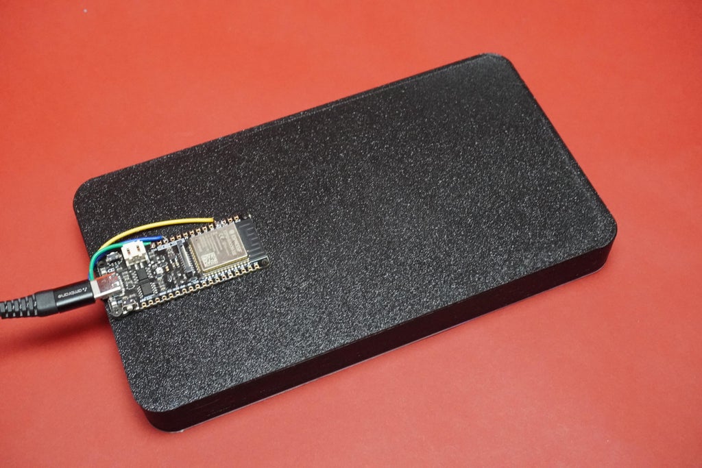
In my initial assembly, I encountered a couple of issues—there wasn't an opening for the ESP32 board, and the height was short by 3mm. However, I've made modifications to the design to address these concerns. For your assembly, you can now place the ESP32 board using the same 2mm screws on the cover, ensuring alignment with the C-type port opening on the housing.
Now, simply snap the cover into the housing; it's designed as a snap fit, making the assembly straightforward. Enjoy your completed Pixo project!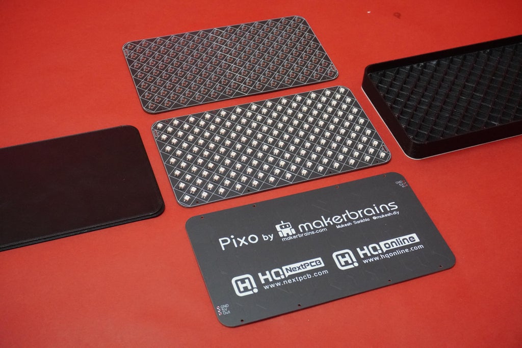

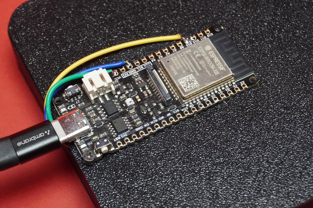
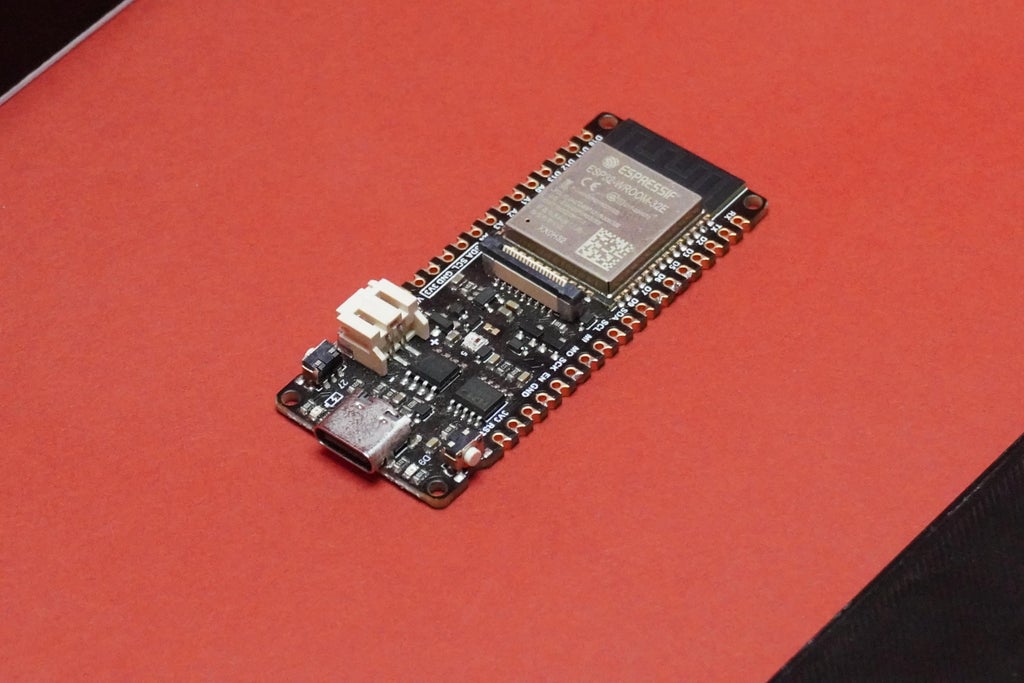
 I opted for the Firebeetle ESP32-S2 from DFRobot as my microcontroller because it comes with both WiFi and Bluetooth capabilities. Currently, the existing code for the matrix doesn't tap into these wireless features; it solely utilizes the fundamental functionality of the microcontroller. This means you can use any other board, such as Arduino or similar, if you prefer.
However, my choice of the ESP32 allows for potential future exploration. I plan to tinker with the software to unlock the wireless capabilities, enabling the matrix to be controlled wirelessly. This opens up exciting possibilities for remote control and enhanced functionality down the line.
Circuit Connection For FireBettle ESP32:
1. Pixo GND~ Pin GND
2. Pixo 5V~Pin Vcc3. Pixo In~Pin D13To code your Pixo, follow these steps:
Install the Arduino IDE and ensure that the ESP32 Board manager is installed. If you're not sure how to do this, you can refer to this article: Installing the ESP32 Board in Arduino IDE.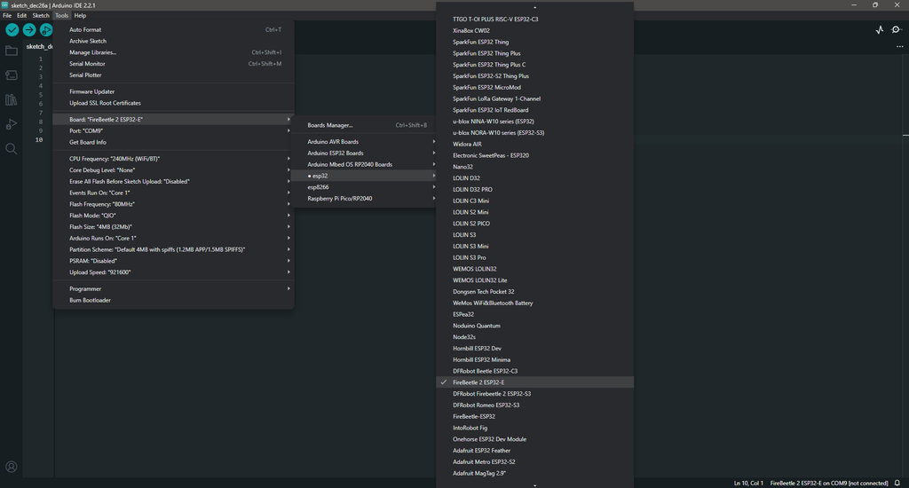
//#define CLK_PIN 4
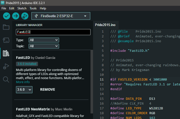
#define LED_TYPE WS2812B
#define COLOR_ORDER RGB
#define NUM_LEDS 163
#define BRIGHTNESS 255
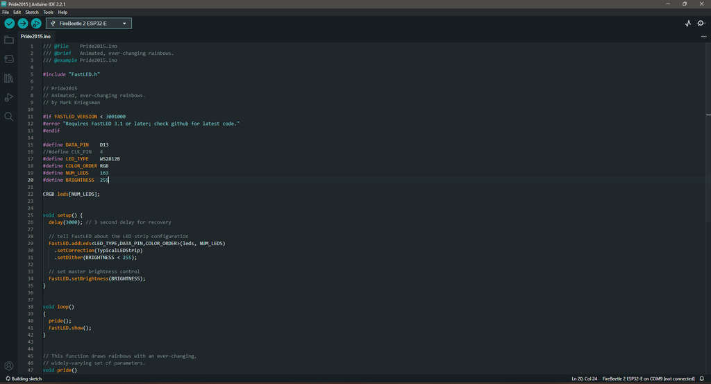
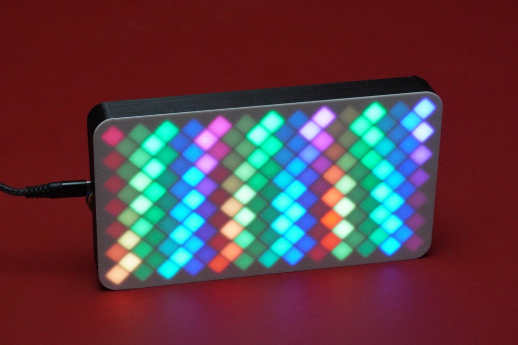
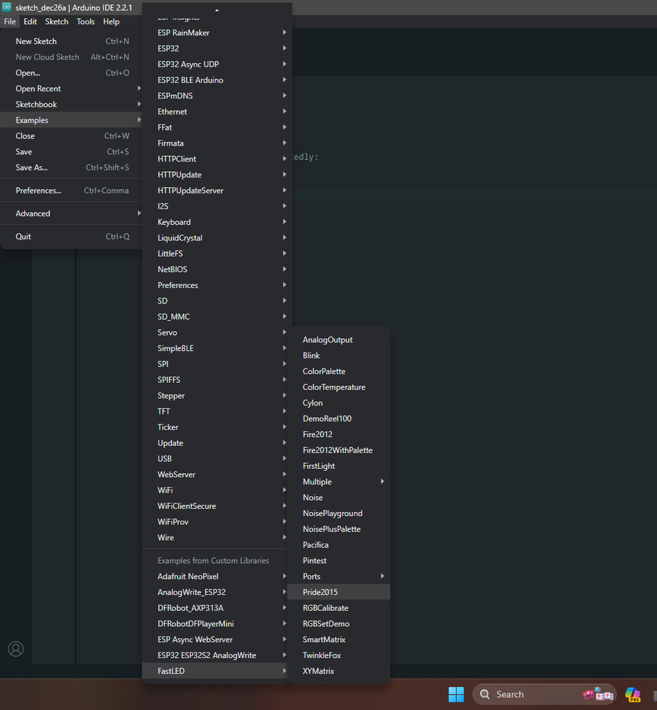
Now, your Pixo should start displaying the Pride2015 example pattern. Feel free to experiment with the code and create your own mesmerizing light patterns for the Pixo using FastLED.
 In conclusion, the Pixo project is a colorful journey of creativity and technology. We designed and 3D printed a cool enclosure, assembled the LED matrix with a custom PCB, and brought it to life with the Firebeetle ESP32-S2 microcontroller. While the initial code showcases dazzling lights, the real excitement lies in the potential to explore wireless features in the future.
This project wasn't just about assembling parts; it was a chance to learn, tinker, and create something unique. Whether you're into coding, electronics, or just love vibrant lights, Pixo is a fantastic way to brighten up your space.
If you run into any questions or face challenges while working on this project, don't hesitate to drop your queries in the comments section. I'm here to help you troubleshoot and find solutions. Happy making!


