


In today's hyper-connected world, nearly every device, from your phone to your fridge is online. But long before the rise of the Internet of Things, the industrial world was already buzzing with serial communication standards like RS-232 (introduced in the 1960s) and protocols like Modbus (invented in 1979). These technologies formed the communication backbone of 20th-century factories, powering legacy machines that still run in thousands of production facilities today.
Here is the thing:
These old machines still work.They’re precise, reliable, and battle-tested.But replacing them is expensive and disruptive.In fact, over 70% of global manufacturing still relies on legacy equipment for core tasks. Upgrading can cost hundreds of thousands of dollars and weeks of downtime.
So... why not make the old smart instead of replacing it?
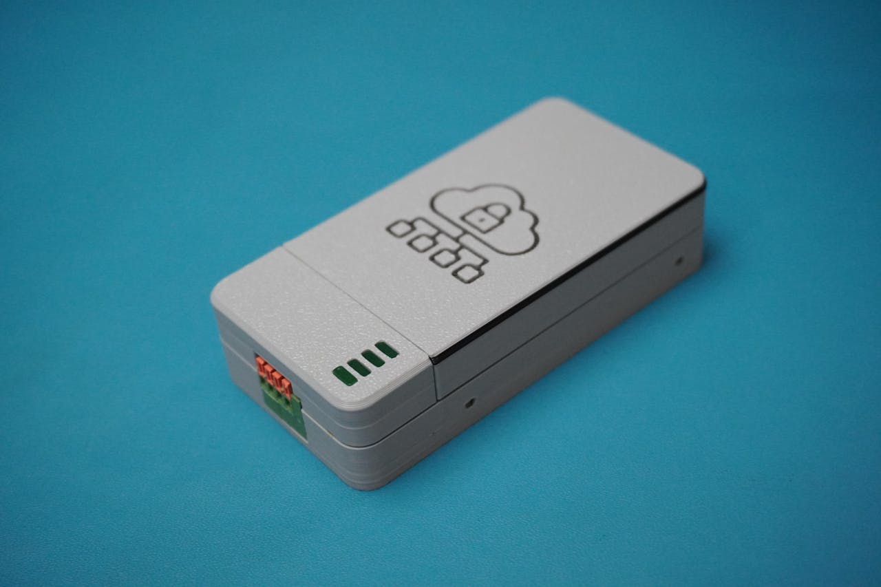
Introducing Retro-Logger
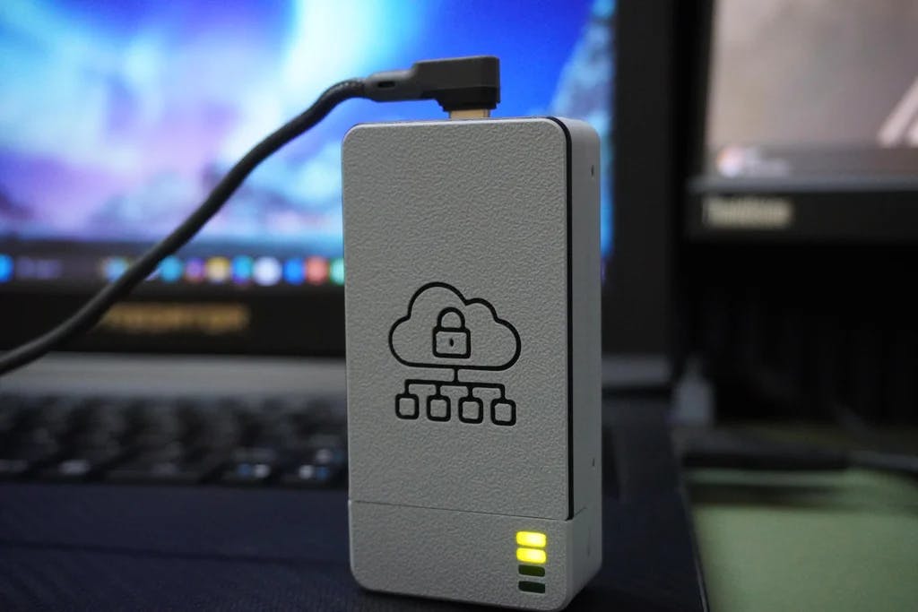
Retro-Logger is a modern-day solution for a late-20th-century problem: how to get decades-old industrial machines to talk to the cloud. It is a secure, ESP32-based IoT data logger that taps into UART serial ports, standard on most legacy equipment, to read data and upload it to the cloud in real-time.
What is Inside?
ESP32 microcontroller4 status LEDs (Power, WiFi, Data Receive, Cloud Sync)4-pin UART connector for direct PLC/machine integrationSecure Boot V2 to prevent tampering and unauthorized firmwareDespite its simplicity, Retro-Logger is powerful. It brings your vintage machinery online, enabling secure data logging to platforms like Google Firebase, all while staying true to its serial roots from the late 20th century.
We will simulate a production line using an Arduino Uno (sending random data via serial), then securely push that data to the cloud. The best part? You can easily adapt Retro-Logger to use RS-485, RS-232, Modbus, MQTT, or HTTP whatever your legacy system requires.


 The Retro-Logger enclosure was designed in Fusion 360 to be both compact and functional. To begin with, I imported the FireBeetle ESP32 3D model (readily available online) to ensure precise fitment. After that, I modeled the LED indicators and the 4-pin connector as separate components based on their actual dimensions.
The enclosure itself consists of three parts:
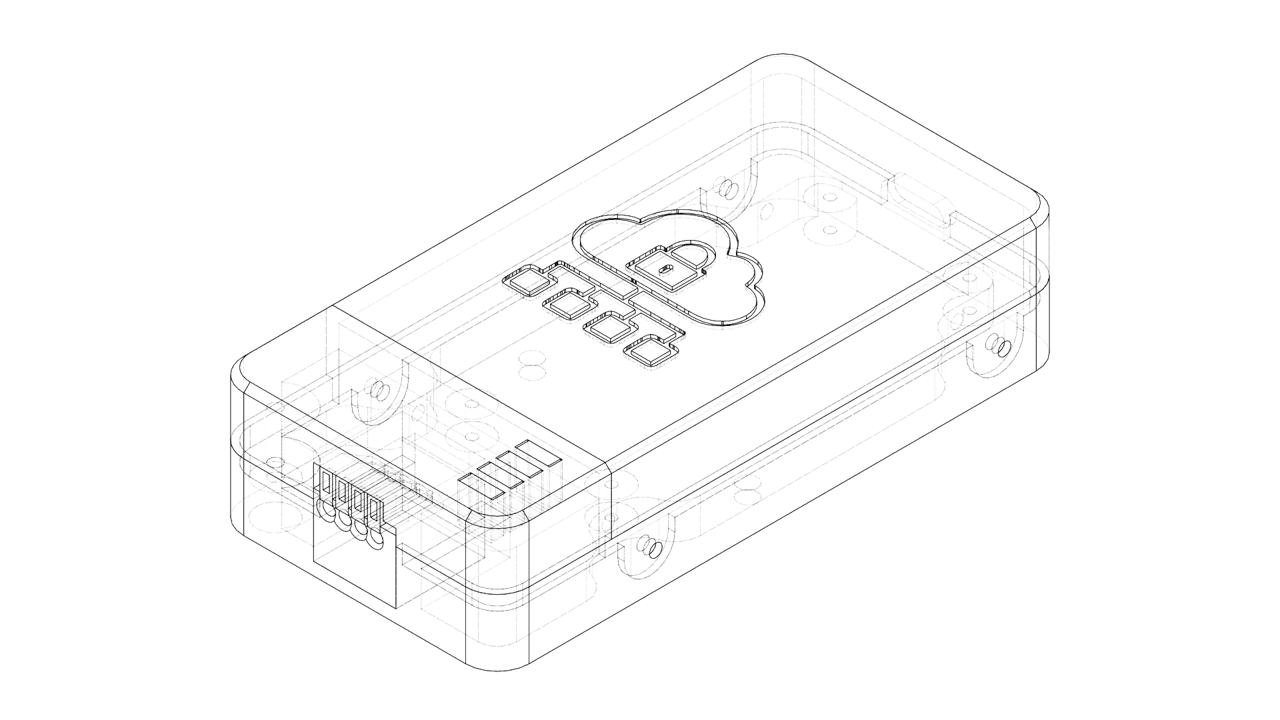
Main Housing – Holds the ESP32 and connector securely in place.LED Mount – Aligns the LEDs for clear visibility and ease of debugging.Top Cover – Neatly seals the device, providing protection while maintaining access for maintenance.The design is intentionally compact, keeping the overall size of Retro-Logger small and suitable for tight spaces on industrial panels or enclosures.
You can:
Download the STL file to 3D print the enclosure as-is, orEdit the Fusion 360 file to customize it for your specific hardware or mounting requirements.Fusion 360 File: Retro-Logger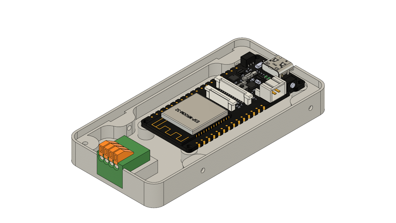


3D print the following parts:
1x Housing.stl1x Mount.stl1x Cover.stlI printed all the parts using my Bambulab P1S 3D printer in off-white filament to give it a classic, retro-tech look. For the cover, I used the filament change technique during the print to achieve a dual-color finish.
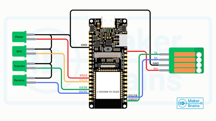
The diagram shows how to connect the status LEDs and the communication connector to the FireBeetle ESP32.
LED Connections (Status Indicators):
Power ~ D7 (GPIO13)WiFi Status ~ D6 (GPIO14)Data Transfer ~ D3 (GPIO26)Data Receive ~ D2 (GPIO25)Common GND ~ GND4-Pin Communication Connector
VCCGNDRXTX


Now that the 3D-printed parts are ready and keeping circuit diagram in mind, let's assemble the LED indicators into the LED Mount.
Place each LED into its designated slot on the LED Mount. If the fit is tight, perfect! If they are a little loose, just use a drop of quick glue to hold them in place.Make sure the cathodes (short legs) of all LEDs are facing the same direction. This will allow you to group the GND connections neatly.Bend all the short legs (cathodes) toward each other and twist them together into a single group.Trim any excess length from the terminals using wire cutters.Cut and strip 5 different colored wires:Black – for GND (common cathode)Other 4 colors – for each signal line (Power, WiFi, Transfer, Receive)Solder the black wire to the grouped cathodes.Solder each colored wire to the anode of each LED.Use heat shrink tubing over each connection to prevent shorts and give a clean finish.Once this is done, your LED assembly is ready to be wired into the ESP32.


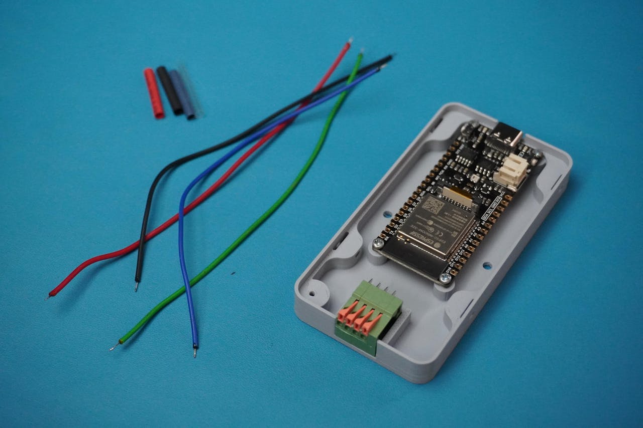
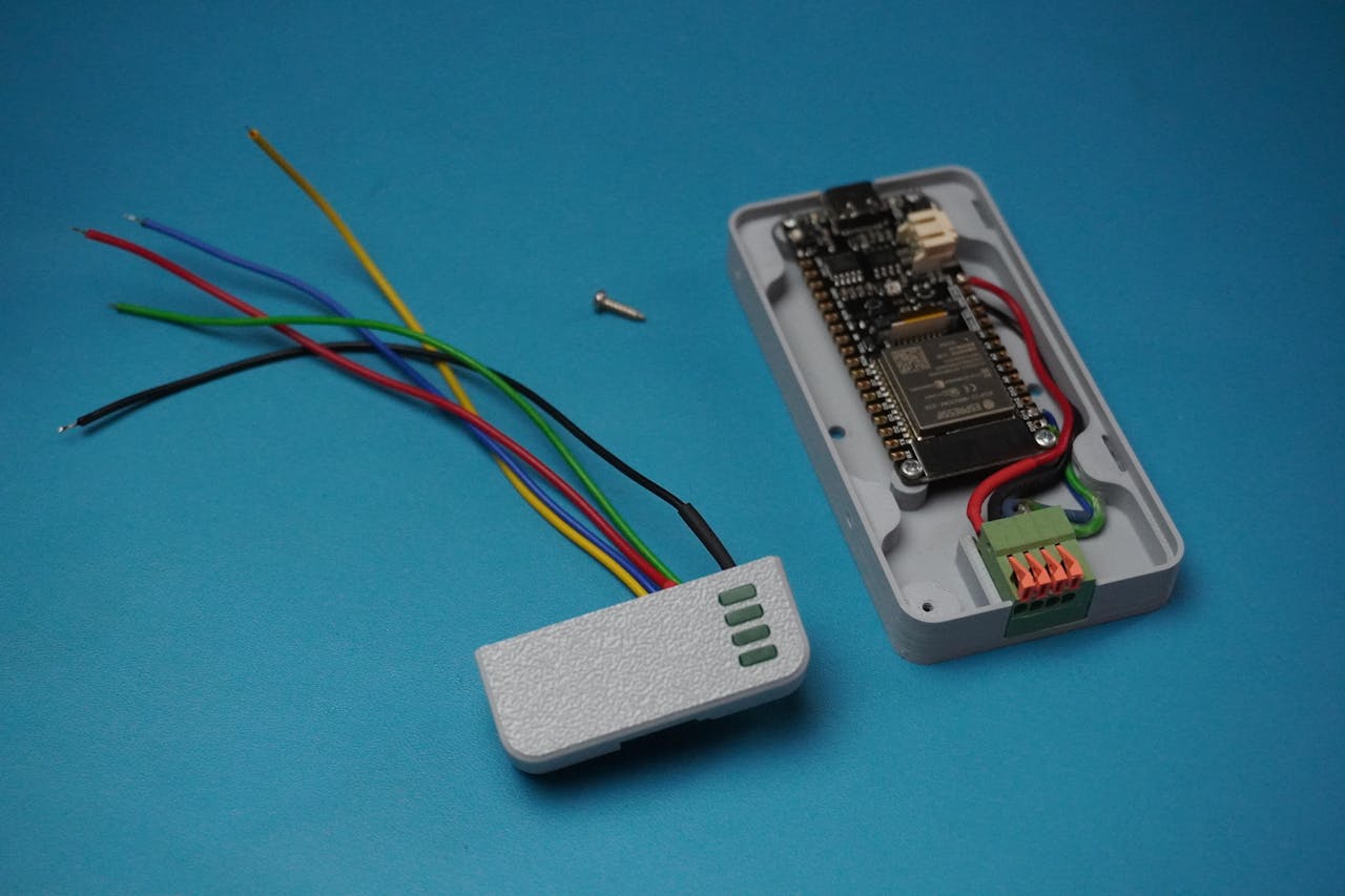
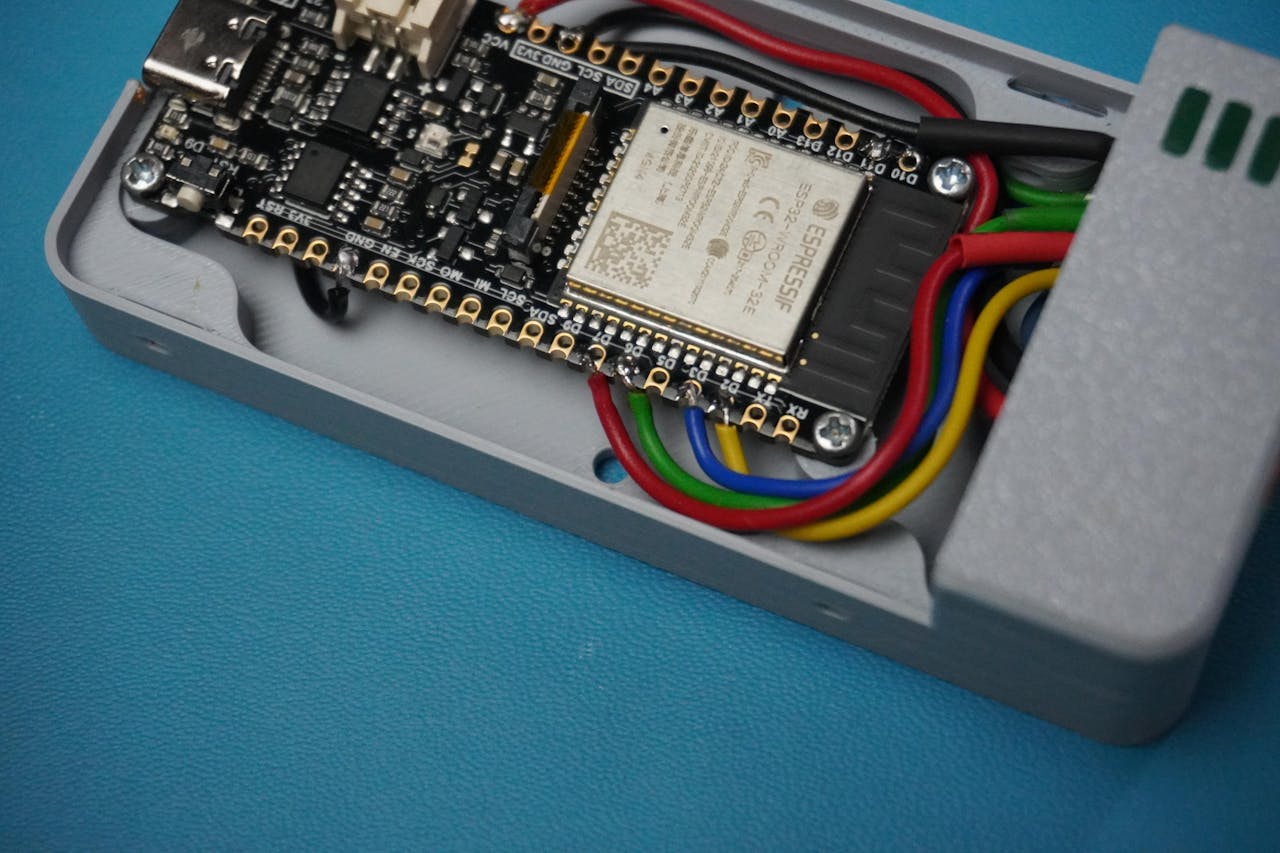
With the LEDs ready and mounted, let's move on to installing the connector and ESP32 board into the Retro-Logger housing.
Apply a small drop of quick glue to the connector slot on the housing.Carefully place the connector into its position and hold it for a few seconds until the glue sets.Align the FireBeetle ESP32 with the mounting holes inside the housing.Use 4 x M2 screws to firmly screw the board in place.


Wire the Communication Connector:
Prepare and solder 4 color-coded wires to the connector terminals:
🔴 Red ~ VCC
⚫ Black ~GND
🔵 Blue ~ RX
🟢 Green ~ TX


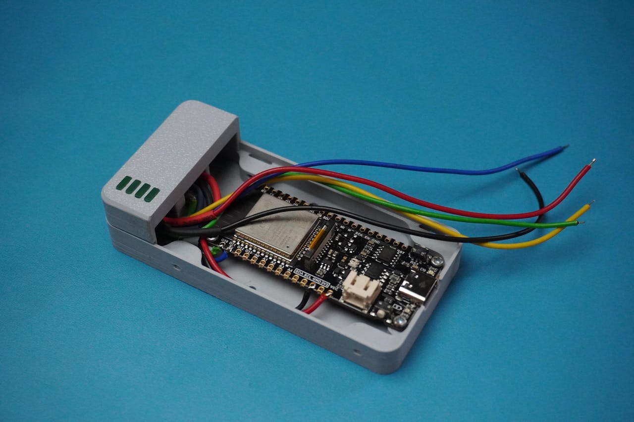
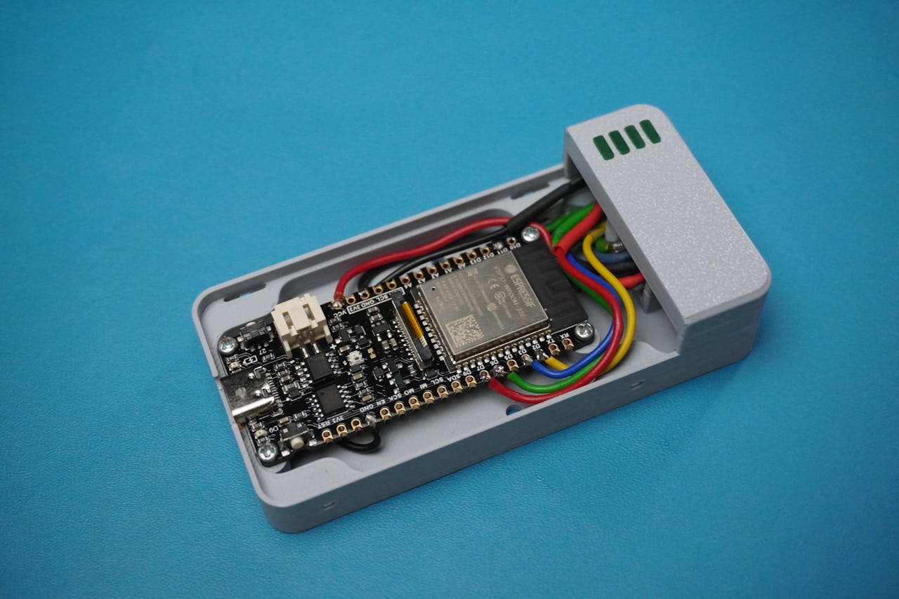
Now that both the Housing Assembly (ESP32 + Connector) and LED Mount Assembly are ready, let's bring everything together.
Align the LED Mount with on top of the Housing.Use 1 x M2 screw to secure the mount in place firmly.Following the circuit diagram from Step 3, carefully solder all the wires to their corresponding ESP32 GPIO pins:Double-check pin mapping and wire colors before soldering.
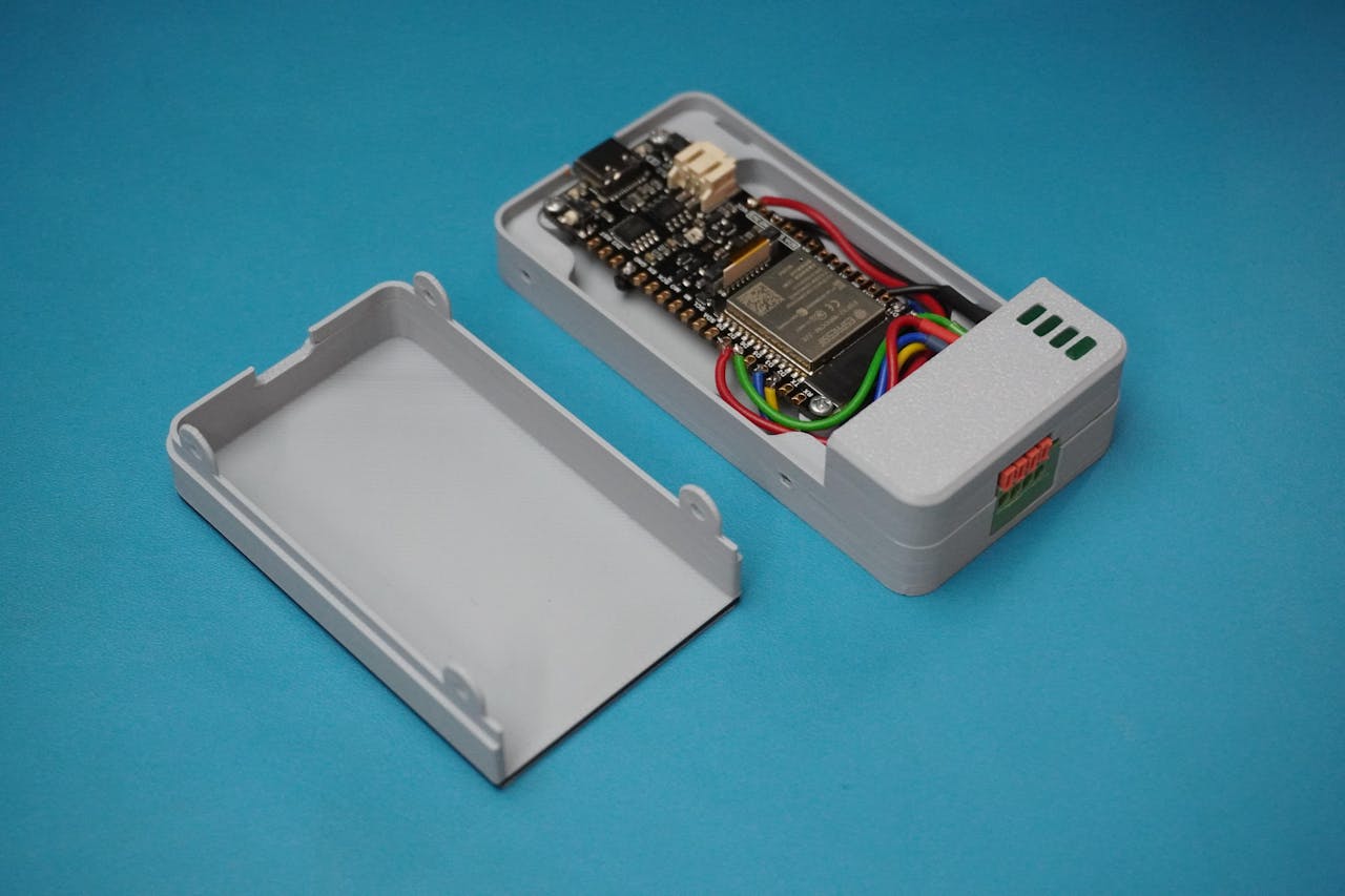
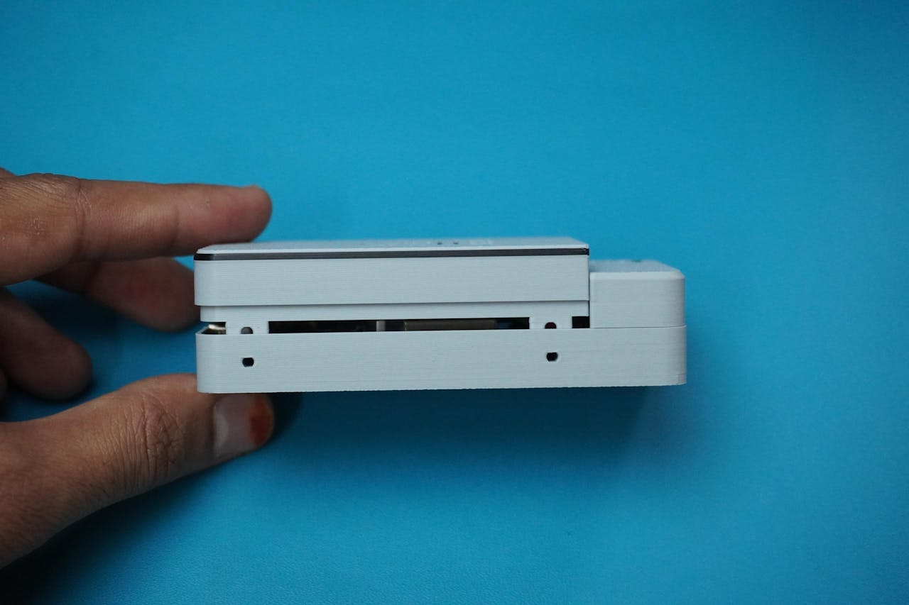
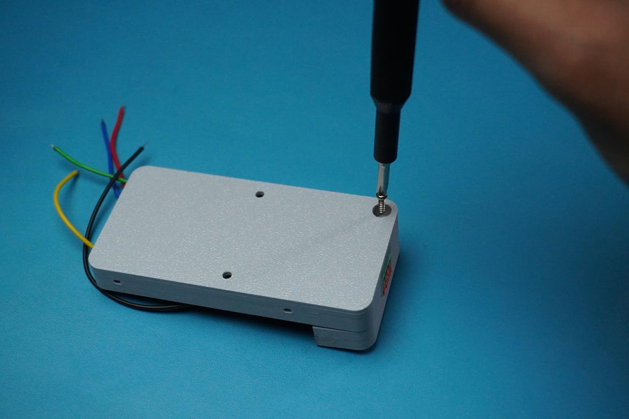
Now that all the wiring and internals are complete, let's finish off the Retro-Logger with the final cover.
Take the Cover part and carefully align it on top of the assembled housing.Press gently but firmly until it snaps into place. The design provides a snug fit, so no screws are absolutely necessary.For extra durability and to make it tamper-resistant, you can secure the cover with 4 x M2 screws on side screw holes provided in the enclosure design.This is especially recommended if your Retro-Logger will be deployed in a production environment with vibration or potential interference.
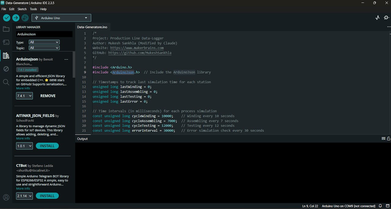
To simulate a real production line generating data for the Retro-Logger, we'll use an Arduino Uno running a data simulation sketch.
This code mimics a Magnetic Relay Switch Component Production & Testing line, generating real-world-like JSON packets and sending them over Serial.
Download the GitHub repo: Retro-LoggerOpen Data-Generatore.ino in Arduino IDE.Connect your Arduino Uno.Install ArduinoJson Library.Select the board (Arduino Uno)Choose the correct COM portClick Upload.Once the code is uploaded, the Uno will begin simulating production line data and printing structured JSON packets over Serial.
What This Code Does?
Simulates 3 key processes:winding (e.g., wire + drum measurements)assembling (unit count per assembly)testing (various pass/fail criteria)Adds realistic variation and fail casesOccasionally injects machine errors to simulate real faultsOutputs data in structured JSON format to the Serial portEach simulated step generates a JSON payload like this:
{
"winding": {
"120425S1WN00001": {
"wire_thickness": 2.05,
"drum_thickness": 12.1,
"wire_ok": 1,
"drum_ok": 1,
"pass": 1,
"fail": 0,
"reason": "-"
}
}
}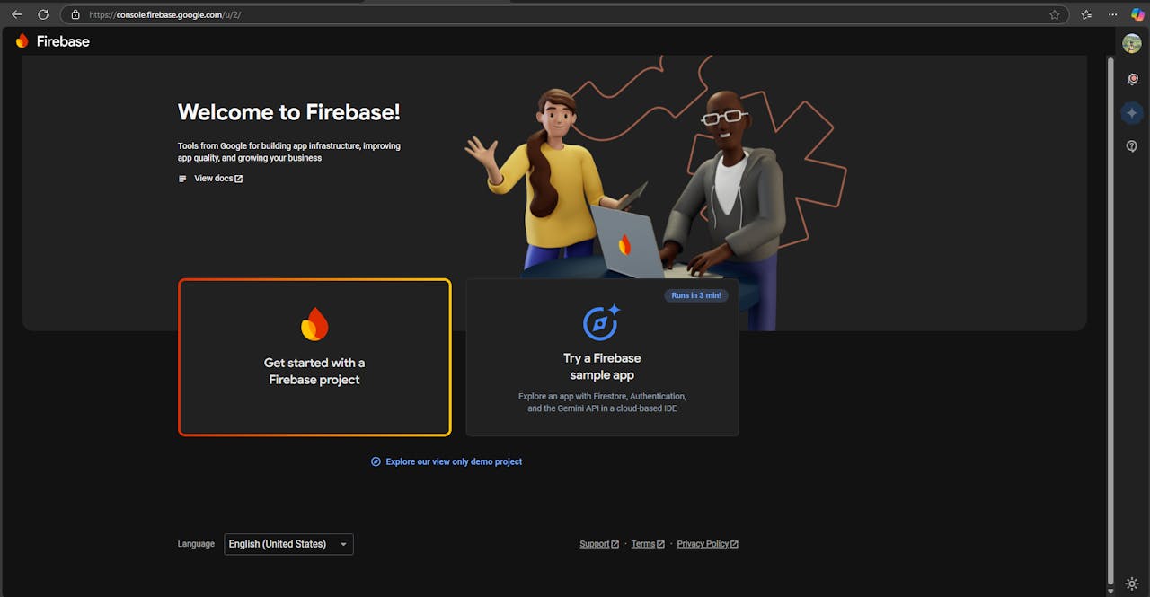

Go to Firebase Console:
Open your browser and navigate to console.firebase.google.com.
Start a New Project:
Click on "Get started" to create a new Firebase project.
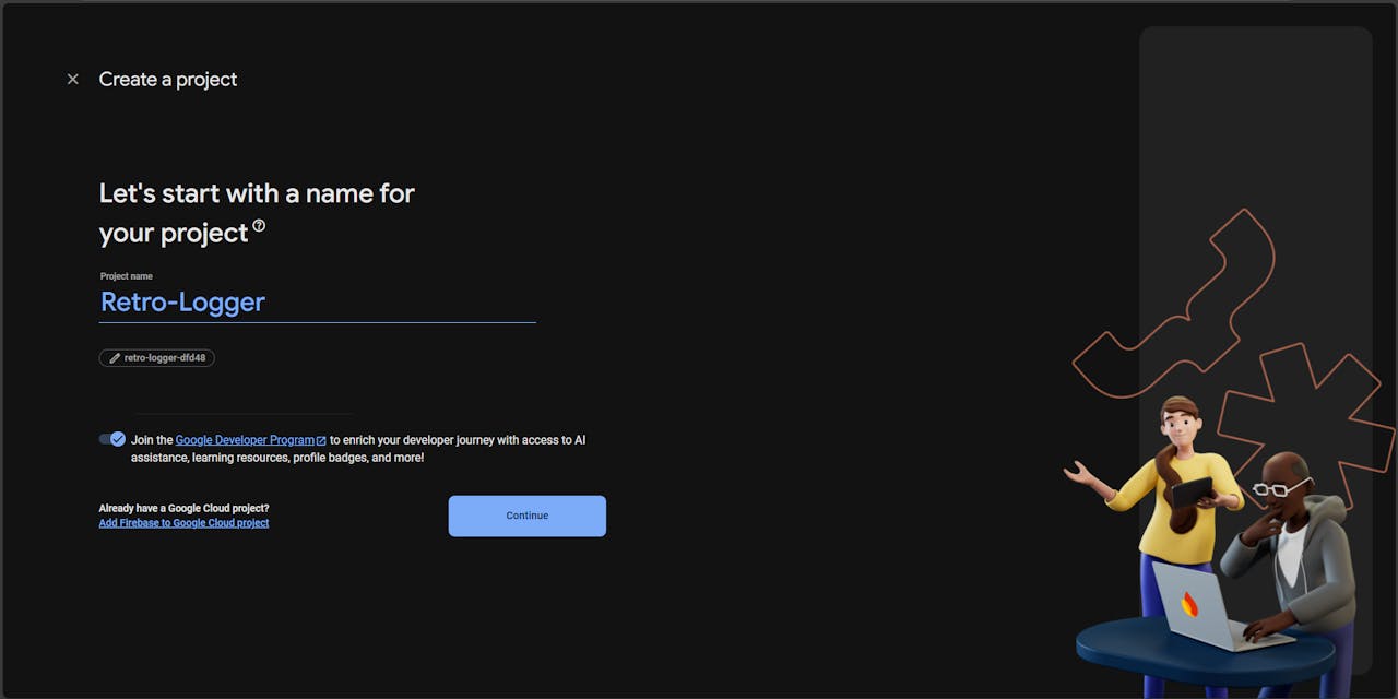
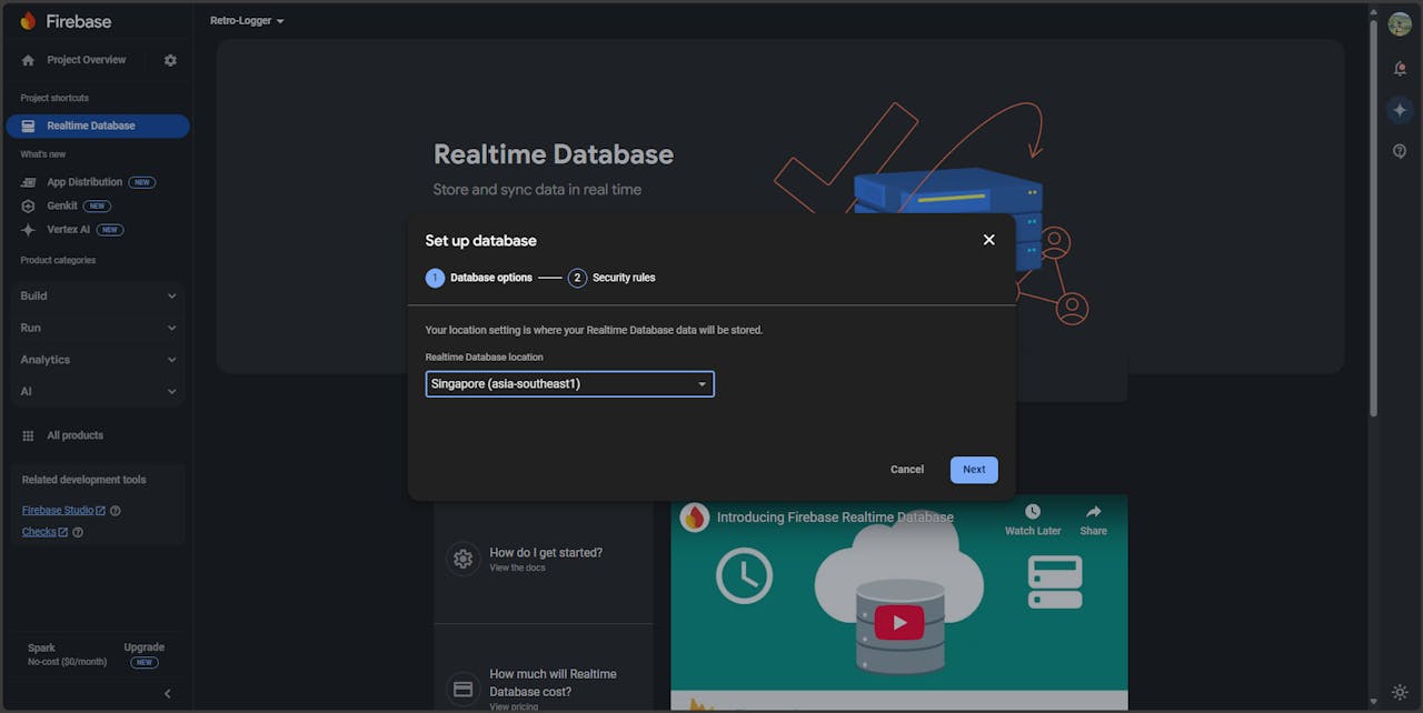
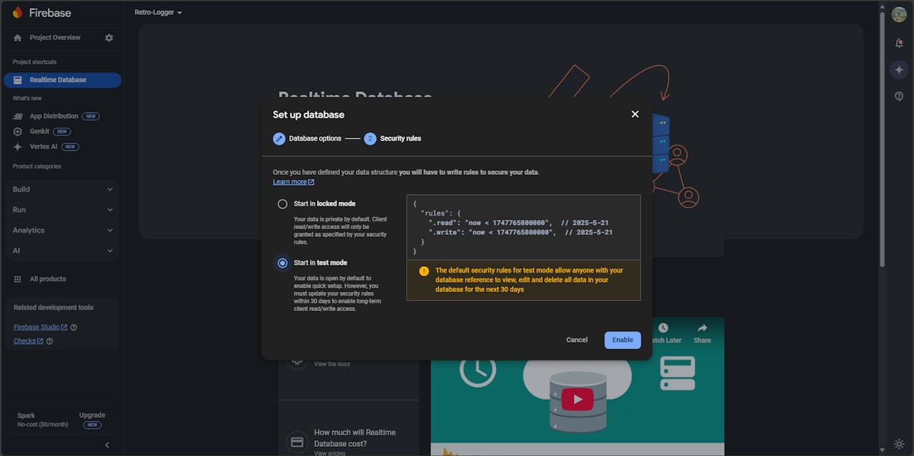
Enter your desired Project Name.Select your Country/Region.Agree to the terms and click "Create Project".Set Up Realtime Database:
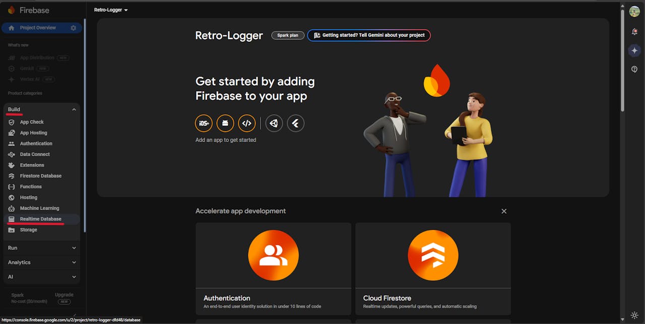

Locate Your Database URL and Secret:
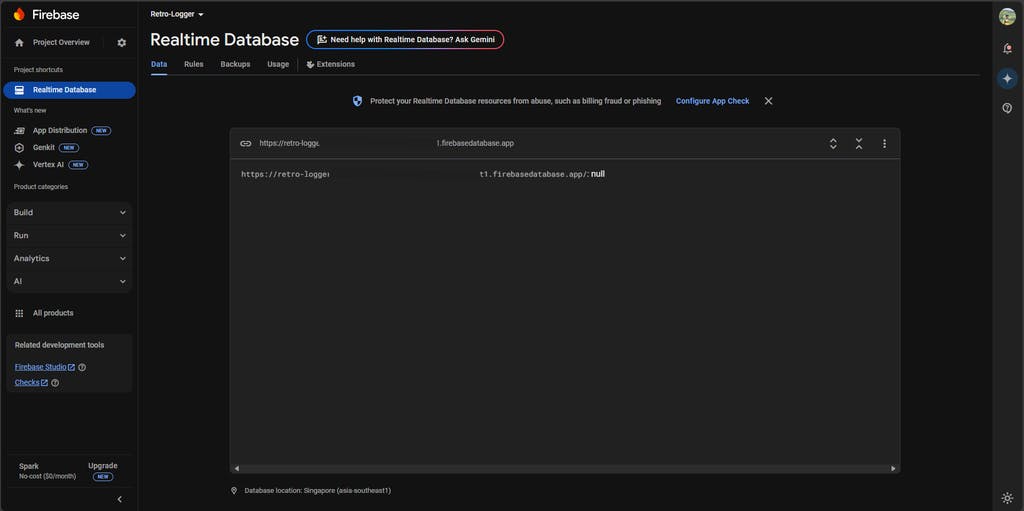
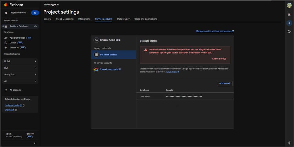 Copy both the Database URL and the Database Secre, you will need them later.
Secure Boot is a critical security feature designed to protect your ESP32 device from unauthorized access and tampering. It ensures that only verified and trusted firmware can run on the device. This means that during the boot process, the ESP32 checks the integrity and authenticity of the firmware before allowing it to execute.
With Secure Boot enabled:
No one can reprogram the device without proper authorization.Unauthorized or malicious firmware is automatically blocked, preventing potential security breaches.For deeper insights into Secure Boot on the ESP32, you can explore these resources:
Thistle Tech: ESP32 Secure Boot v2 - Part 1Thistle Tech: ESP32 Secure Boot v2 - Part 2This Project Is Powered by Thistle Technologies
Thistle makes it easy to secure your embedded devices with production-grade tools and best practices. From enabling Secure Boot to setting up encrypted OTA (Over-The-Air) updates, Thistle provides everything you need to lock down your firmware and protect your product, without slowing down your development process.
If you're serious about device security and want to save time avoiding the pitfalls of manual setup, check out Thistle's Secure Boot guide for ESP32 and explore their other powerful tools for embedded security.
⚠️ Warning: Secure Boot Enabled - Authenticated Firmware Only
Before proceeding, it’s important to understand that once an ESP32 is fused, its security state is permanently changed, this process is irreversible.
If you have already fused your ESP32 during development using test keys or temporary credentials, you cannot reuse that same device for production.
For production deployment, you will need a fresh, unfused ESP32, as Step 14 involves blowing the eFuses using a different firmware signing key securely managed by Thistle.tech. This ensures your production firmware is cryptographically signed and the device is tamper-resistant.
This means:
Only properly signed and authenticated firmware will be accepted by the device.
You cannot flash new code or reprogram the device using Arduino IDE, PlatformIO, or idf.py flash unless the firmware is signed with the correct private key.
This is by design.
If you lose the private key used to sign your firmware, you will not be able to update or recover your device.
Choose Your Path: With or Without Secure Boot
You have two ways to use the Retro-Logger, depending on your goals:
Option 1: Secure Boot (Recommended for Production)
If you're building a product or care about protecting your firmware:
Enable Secure Boot V2 using the Thistle workflowSign all firmware before flashingDevice will only accept authenticated updatesGreat for preventing tampering, unauthorized reprogramming, or reverse engineeringBest for: Production devices, commercial products, or anything that needs strong security.
Option 2: Standard ESP32 Workflow
If you're just experimenting, prototyping, or learning:
You can skip Secure BootSimply install ESP-IDF or use the Arduino IDEBurn code directly using idf.py flash or Arduino's upload buttonEasier and quicker for development, but less secureBest for: Hobby projects, rapid testing, or when you don't need firmware protection.
You can always start development without Secure Boot and enable it later just make sure you are fully prepared before blowing the eFuses! Otherwise, you will need two ESP32s: one for development and another for production.
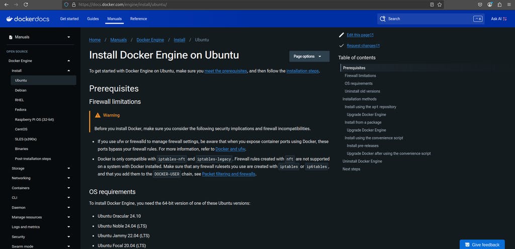
We will use Docker to simplify and standardize the build environment. Follow these steps to install Docker on an Ubuntu-based system.
Official Guide: Docker Installation on Ubuntu
1. Add Your User to the Docker Group: This allows you to run Docker without using sudo every time.
sudo usermod -aG docker $USER
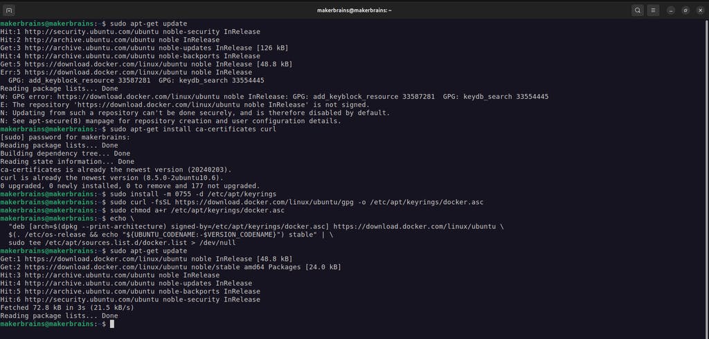
newgrp docker2. Set Up Docker’s Official GPG Key
sudo apt-get update
sudo apt-get install ca-certificates curl
sudo install -m 0755 -d /etc/apt/keyrings
sudo curl -fsSL https://download.docker.com/linux/ubuntu/gpg -o /etc/apt/keyrings/docker.asc
sudo chmod a+r /etc/apt/keyrings/docker.asc
3. Add Docker Repository to Apt Sources
echo \
"deb [arch=$(dpkg --print-architecture) signed-by=/etc/apt/keyrings/docker.asc] https://download.docker.com/linux/ubuntu \
$(. /etc/os-release && echo "${UBUNTU_CODENAME:-$VERSION_CODENAME}") stable" | \
sudo tee /etc/apt/sources.list.d/docker.list > /dev/null
4. Install Docker Engine
sudo apt-get update
sudo apt-get install docker-ce docker-ce-cli containerd.io docker-buildx-plugin docker-compose-plugin
5. Verify Installation: Run the following command to check if Docker is working:
dockerYou should see Docker's help message, confirming that it’s installed correctly.
For more information about Docker Engine visit: docs.docker.com/engine
1. Start by cloning the official Thistle Tech ESP32 development environments repository:
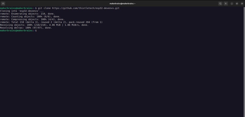
git clone https://github.com/thistletech/esp32-devenvs.git
cd esp32-devenvs/esp32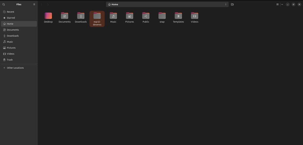
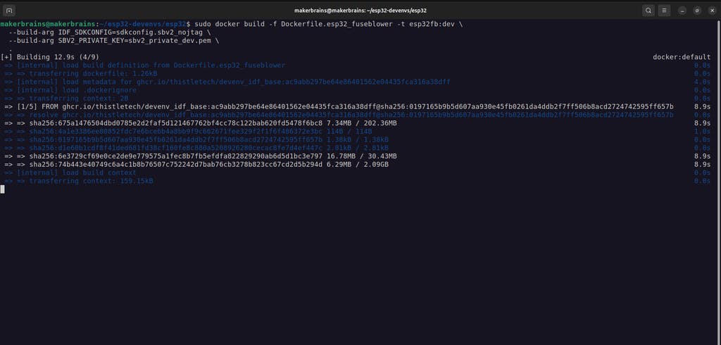
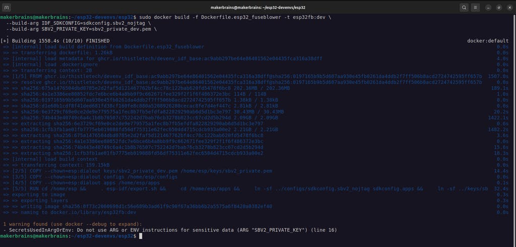
2. Build the Docker image for fuse blowing and firmware signing:
sudo docker build -f Dockerfile.esp32_fuseblower -t esp32fb:dev \
--build-arg IDF_SDKCONFIG=sdkconfig.sbv2_nojtag \
--build-arg SBV2_PRIVATE_KEY=sbv2_private_dev.pem \
.
This is going to take some time based on your internet speed.
3. Connect your unfused ESP32 development board via USB.
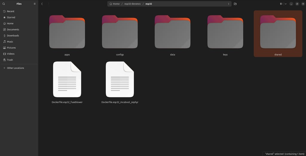
4. Create a shared folder and allow access:
mkdir -p shared
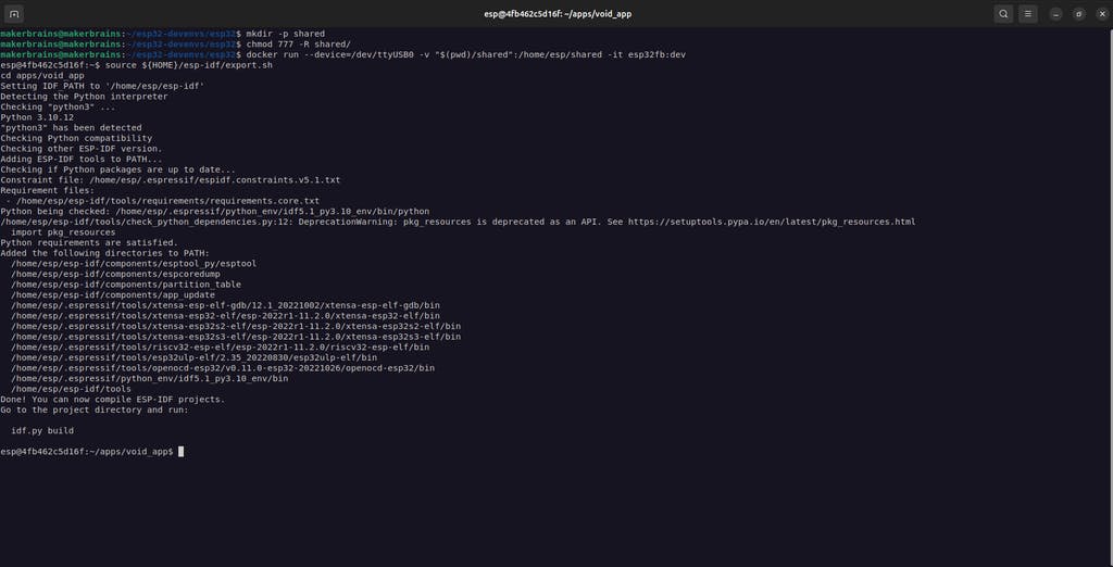
chmod 777 -R shared/5. Launch the Docker Container
docker run --device=/dev/ttyUSB0 -v "$(pwd)/shared":/home/esp/shared -it esp32fb:devReplace /dev/ttyUSB0 with the appropriate device node if needed
6. Blow Secure Boot eFuses
Inside the container:source ${HOME}/esp-idf/export.sh
cd apps/void_appesptool.py --chip esp32 \
--port=/dev/ttyUSB0 \
--baud=460800 \
--before=default_reset \
--after=no_reset \
--no-stub \
write_flash \
--flash_mode dio \
--flash_freq 80m \
--flash_size keep \
0x1000 build/bootloader/bootloader.binesptool.py -c esp32 \
-p /dev/ttyUSB0 \
-b 460800 \
--before=default_reset \
--after=hard_reset \
--no-stub \
write_flash \
--flash_mode dio \
--flash_freq 80m \
--flash_size keep \
0x20000 build/void_app.bin \
0x10000 build/partition_table/partition-table.bin7. Use the ESP-IDF monitor tool to view output:
idf.py -p /dev/ttyUSB0 monitorYou should see logs like:
I'm the void app. I do nothing.
I (206) secure_boot_v2: Verifying with RSA-PSS...
I (212) secure_boot_v2: Signature verified successfully!
This confirms the Secure Boot setup is working correctly and the signature is valid.
Helpful Resources:
Secure Boot V2 BlogESP32 Secure Boot Docs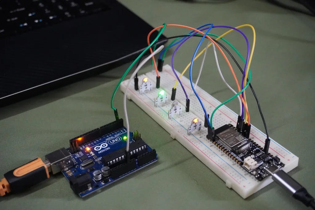
Now it's time to build and securely sign your actual application - the Retro-Logger, which reads data over UART and sends it to Firebase via HTTPS.
1. Open a New Terminal & Launch Docker
Navigate to your working directory:cd esp32-devenvs/esp32docker run --device=/dev/ttyUSB0 -v "$(pwd)/shared":/home/esp/shared -it esp32fb:dev. esp-idf/export.sh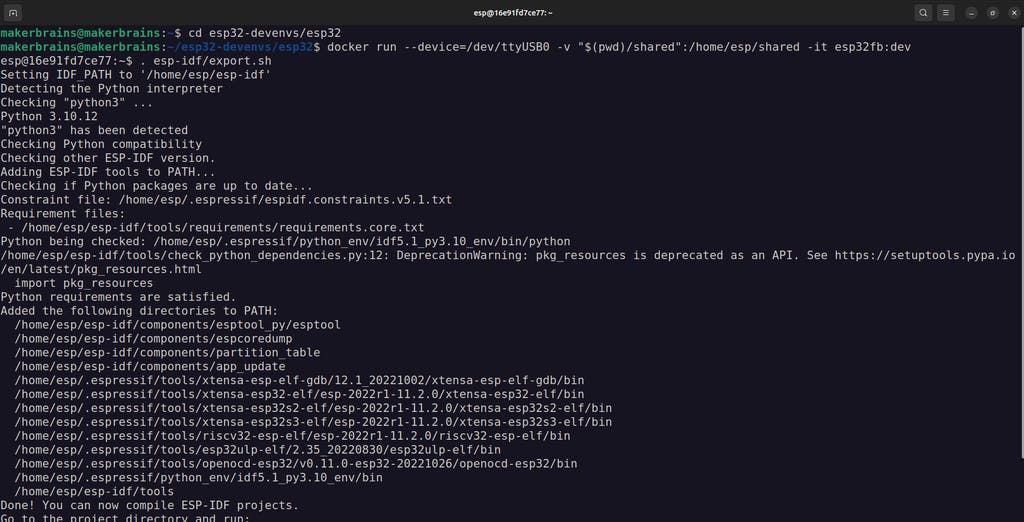
2. Prepare the Application Code
Copy the data-logger folder (from the GitHub repo we downloaded earlier) into the shared/ directory on your host system:
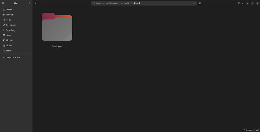
esp32-devenvs/esp32/shared/data-logger/Open the file main/data-logger.c in a text editor and enter your WiFi and Firebase credentials:
// WiFi credentials
#define WIFI_SSID "Your_SSID"
#define WIFI_PASSWORD "Your_PASSWORD"

// Firebase configuration
#define FIREBASE_HOST "your-database.firebaseio.com"
#define FIREBASE_AUTH "your_database_secret"
These values were copied earlier in Step 9 from Firebase.
Save and close the file.
3. Move and Configure the App in the Docker Container
Inside the container:
cp -r shared/data-logger/ apps/
cd apps/data-logger
Clean up old configs and set up secure boot configs
rm -rf sdkconfig sdkconfig.ci
ln -s ../sbv2_private_pem.app sbv2_private.pem
ln -s ../sdkconfig.apps sdkconfig.defaults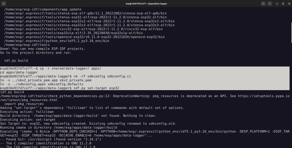
Target ESP32 and build the firmware
idf.py set-target esp32
idf.py build
4. Connect Your Hardware
Wire the ESP32 to the Arduino Uno as follows:
🔵 RX (D11) > TX
🟢 TX (D10) > RX
⚫ GND > GND
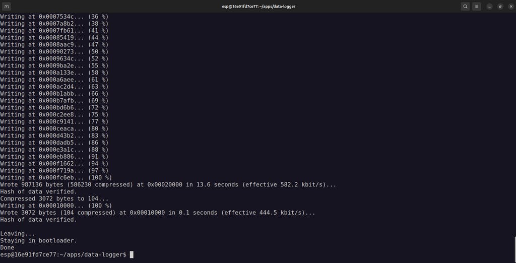
5. Flash the signed firmware to your ESP32:
idf.py flash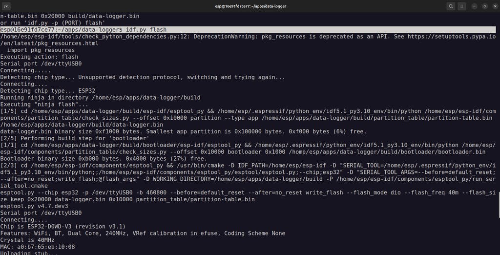
6. Monitor the serial output:
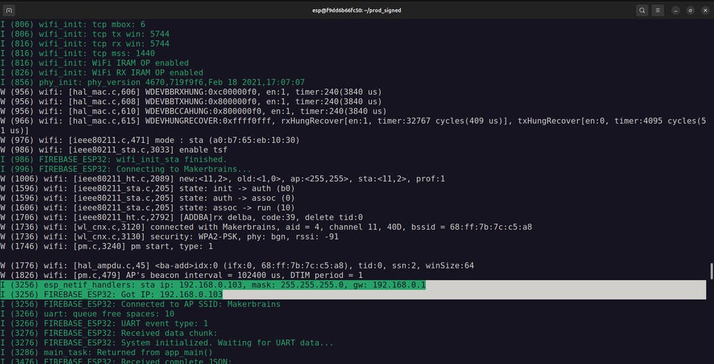
idf.py monitorIf everything is connected and configured properly, the terminal should show:
Data being received over UART from the ArduinoProperly parsed JSON payloadsSecure HTTPS transmission to your Firebase Realtime Database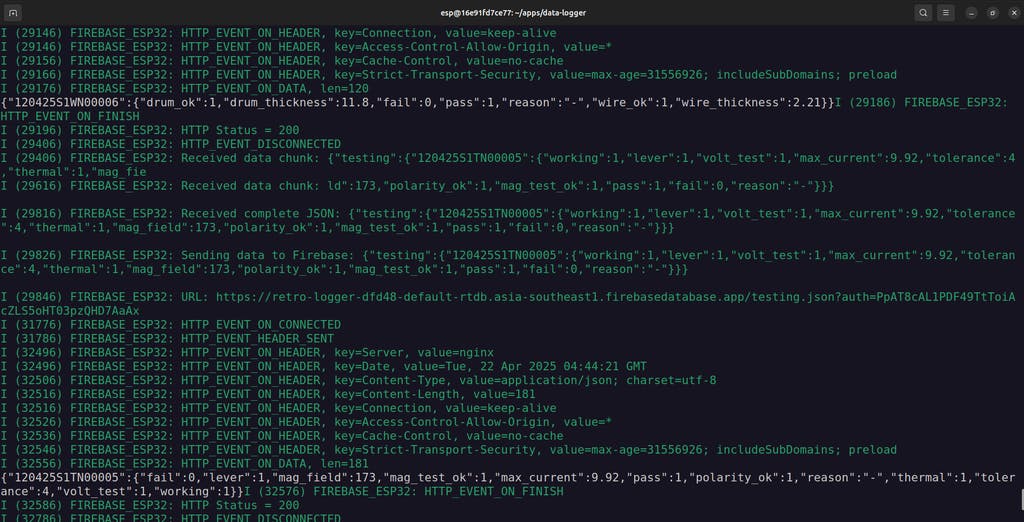

After testing your application in development mode, it's time to sign and flash production-ready firmware with Secure Boot V2 enabled.
1. Copy Firmware Files to Host MachineConnect the ufused ESP32 production device (Retro Logger) and run the Docker container.
Build the firmware again as we did in development mode.
Inside the Docker container, copy the necessary build artifacts to the shared folder so they’re accessible from the host:
cp apps/data-logger/build/partition_table/partition-table.bin shared/
cp apps/data-logger/build/bootloader/bootloader.bin shared/
cp apps/data-logger/build/data-logger.bin shared/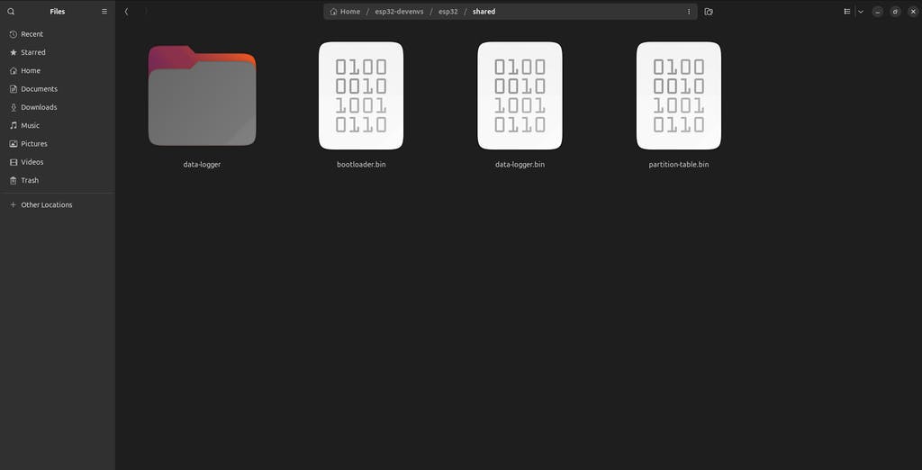
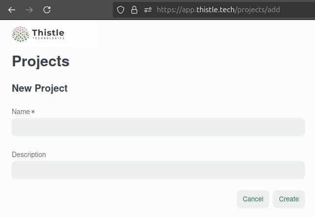
2. Sign Firmware Using Thistle Control Center
On your host machine, open a browser and go to the Thistle Control Center.Create a new project (if you haven't already).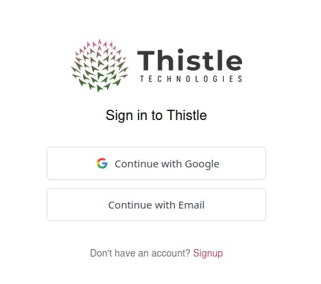

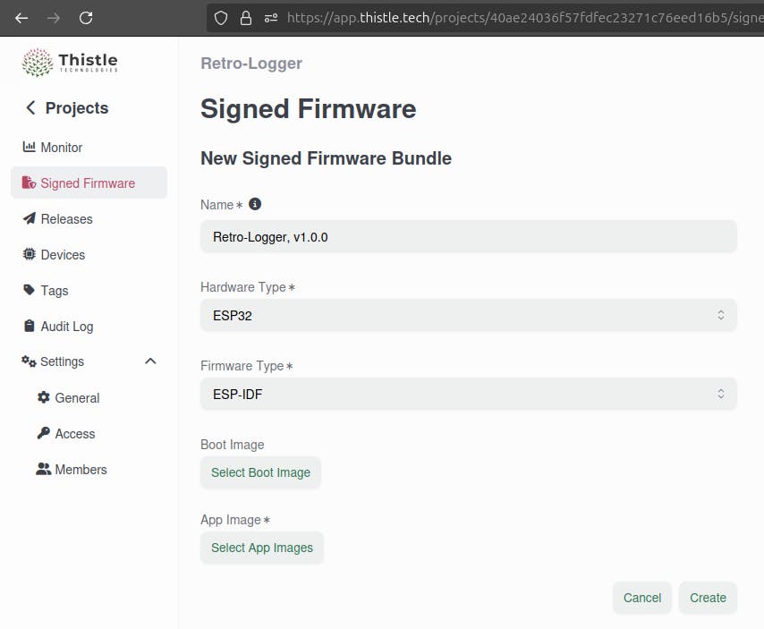
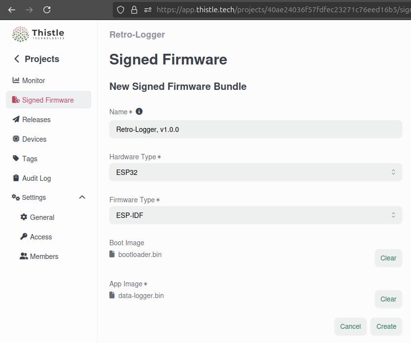
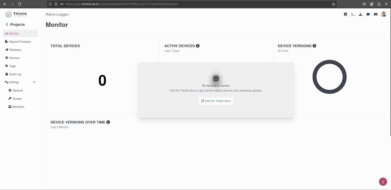 Go to the “Signed Firmware” section.Click the “+ Signed Firmware Bundle” button.Fill out the form:Name: Anything you like (e.g., Retro-Logger v1.0.0)Hardware Type: ESP32Firmware Type: ESP-IDFUpload bootloader.bin and data-logger.bin from the shared folderClick Create.
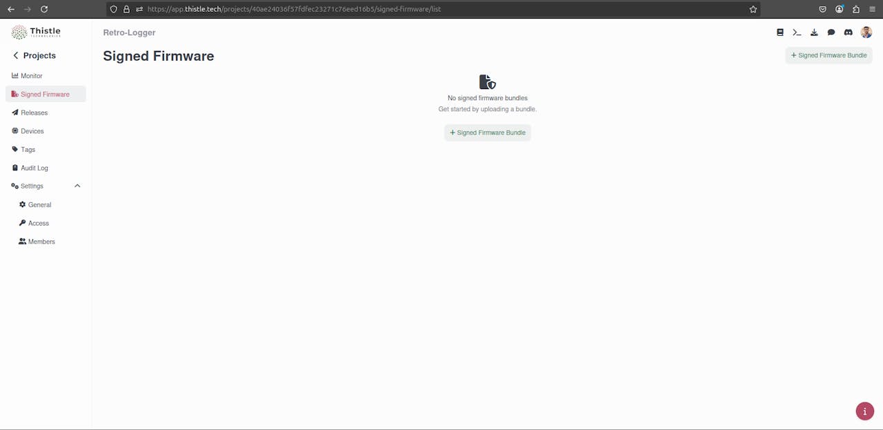


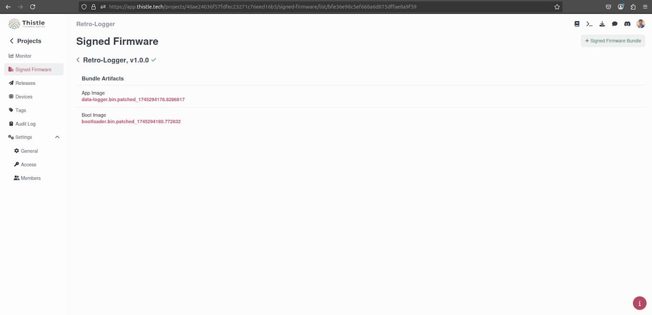
Once the signing process completes, download the signed production firmware files from Thistle:
bootloader.bin.patched_Move them to your shared folder so the Docker container can access them.

3. Flash the Signed Production Firmware
Back inside the Docker container:
mkdir -p prod_signed/
mv shared/data-logger.bin.patched_<timestamp> shared/bootloader.bin.patched_<timestamp> shared/partition-table.bin prod_signed/
source ${HOME}/esp-idf/export.sh
cd prod_signed/
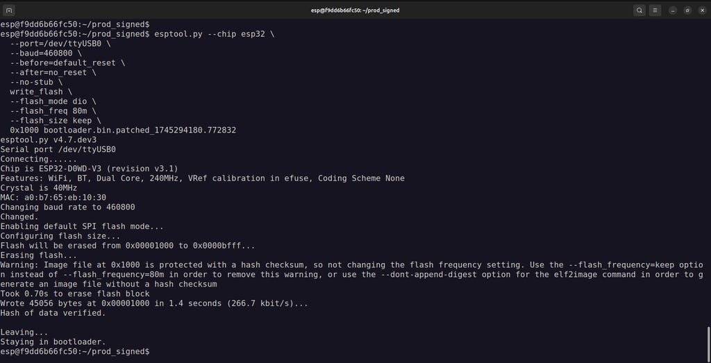
Flash the Signed Bootloader:
esptool.py --chip esp32 \
--port=/dev/ttyUSB0 \
--baud=460800 \
--before=default_reset \
--after=no_reset \
--no-stub \
write_flash \
--flash_mode dio \
--flash_freq 80m \
--flash_size keep \
0x1000 bootloader.bin.patched_<timestamp>
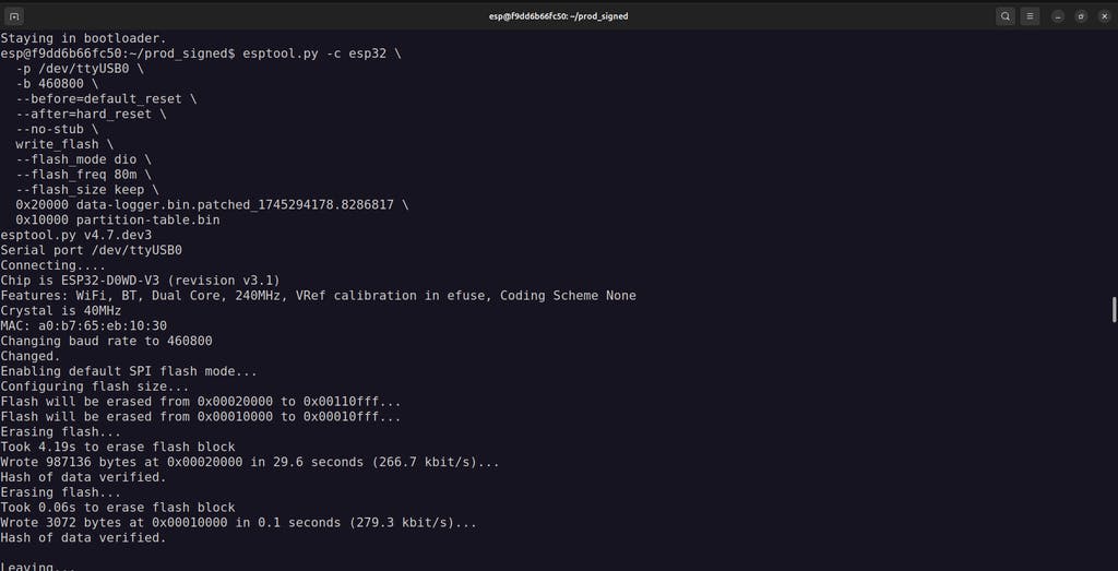
Flash the Signed Application and Partition Table:
esptool.py -c esp32 \
-p /dev/ttyUSB0 \
-b 460800 \
--before=default_reset \
--after=hard_reset \
--no-stub \
write_flash \
--flash_mode dio \
--flash_freq 80m \
--flash_size keep \
0x20000 data-logger.bin.patched_<timestamp> \
0x10000 partition-table.bin
Replace
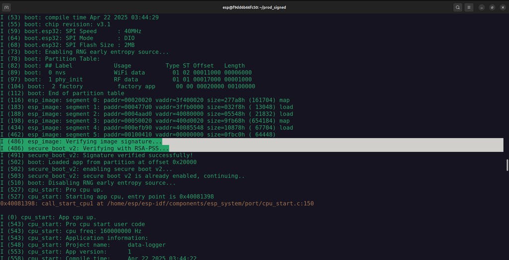
4. Monitor and Verify
Now, monitor the output to verify everything is working:
cd ${HOME}/apps/data-logger/
idf.py -p /dev/ttyUSB0 monitor
You should see logs similar to before, but now running fully signed, production firmware protected by Secure Boot V2.

Note for Future Flashing:
When flashing production devices in the future, you only need to flash the signed application (data-logger.bin.patched_...) and the partition table.
You can skip flashing the signed bootloader - this only needs to be done once per device unless you’re updating the bootloader.

Conclusion - Old Machines, New Tricks

With Retro-Logger, you have successfully:
✔ Connected legacy machines to the cloud
✔ Built a secure data logger with ESP32
✔ Used serial communication to capture real-time data
✔ Protected your firmware with Secure Boot
✔ Leveraged Firebase for easy cloud integration
This project proves that you don’t need to replace reliable old equipment, you can upgrade it.
By combining time-tested technology like IoT with cutting-edge tools like Secure Boot and cloud databases, you have created a modern, secure, and cost-effective IoT solution.
The future of industrial innovation isn’t always about buying new machines, it's about making the old ones smarter.
If you enjoyed this project, don't forget to hit the like button and leave a comment below.
Thank you! See you next time ;)


