
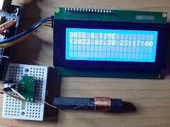
In this tutorial we will learn how to use the DCF77 Radio Clock module using Arduino to display the date and time on the LCD display.
Software apps and online services
- Arduino IDE
- Visuino
Story
Note that the signal strength will depend on your location and it might take a while to receive the signal if you are located far away from the radio station.
You can learn more about the DCF77 here
Step 1: What You Will Need

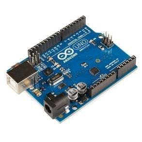


- Arduino UNO (or any other Arduino or ESP)
- Optional LCD I2C Display
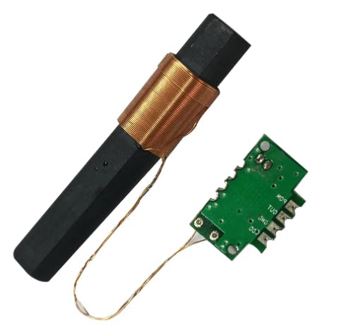
- DCF77 Module link
- Jumper wires
- Breadboard
- Visuino program: Download Visuino
Step 2: The Circuit
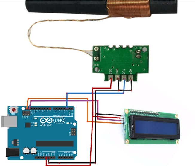
- Connect LCD Display pin [SCL] to Arduino pin [SCL]
- Connect LCD Display pin [SDA] to Arduino pin [SDA]
- Connect LCD Display pin [VCC] to the Arduino positive pin [5V]
- Connect LCD Display pin [GND] to the Arduino pin [GND]
- Connect Arduino Digital pin [2] to the DCF77 pin [Out]
- Connect Arduino pin [5V] to the DCF77 pin [VCC]
- Connect Arduino pin [GND] to the DCF77 pin [GND]
- Connect Arduino pin [GND] to the DCF77 pin [PON]
Note: Pin PON must be connected to Logic False to be Enabled, you can also control it using the Arduino Digital pin
Step 3: Start Visuino, and Select the Arduino UNO Board Type


Start Visuino as shown in the first picture Click on the "Tools" button on the Arduino component (Picture 1) in Visuino When the dialog appears, select "Arduino UNO" as shown on Picture 2
Step 4: In Visuino Add Components

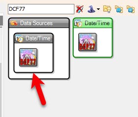
- Add "DCF77" component
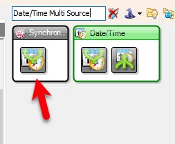
- Add "Date/Time Multi Source" component
- Add "Liquid Crystal Display (LCD)
- I2C" component
Step 5: In Visuino Set Components


- You can set your time zone by selecting "RadioTime1" and in the properties window set "Time Zone Offset (H)"
- You can connect "RadioTime1" pin [Out] directly to the Arduino Serial pin and get the Date & Time values to the terminal window.
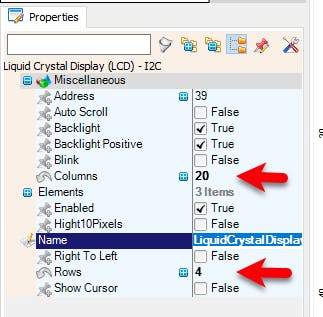
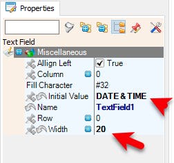
- If you are going to use the LCD I2C then select "LiquidCrystalDisplay1" and in the properties window set "Columns" to 20 and "Rows" to 4, Columns and Rows depends on the type of your Display some only have 16 columns and 2 Rows, then double click on the "LiquidCrystalDisplay1" and in the "Elements" window drag "Text Field" to the Left side and in the properties window set "Width" to 20 and "Initial Value" to Date & Time
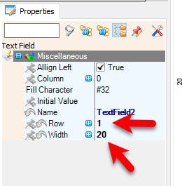
- In the "Elements" window drag another "Text Field" to the Left side and in the properties window set "Width" to 20 and "Row" to 1
- Close the "Elements" window
Step 6: In Visuino Connect Components

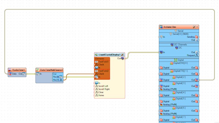
- Connect Arduino digital pin [2] to "RadioTime1" pin [Data]
- Connect "RadioTime1" pin [Out]" to "DateTimeMultiSource1" pin[In]
- Connect "DateTimeMultiSource1" pin[0] to "LiquidCrystalDisplay1" > "TextField2" pin [In]
- Connect "DateTimeMultiSource1" pin[0] to "LiquidCrystalDisplay1" > "TextField2" pin [Clock]
- Connect "LiquidCrystalDisplay1" pin I2C [Out] to Arduino pin I2C [In]
Step 7: Generate, Compile, and Upload the Arduino Code

In Visuino, at the bottom click on the "Build" Tab, make sure the correct port is selected, then click on the "Compile/Build and Upload" button.
Step 8: Play
If you power the Arduino module, The Display will show the Date & Time that it will receive using the DCF77 module, note that it may take a while to receive the DCF77 signal.
Congratulations! You have completed your project with Visuino. Also attached is the Visuino project, that I created for this tutorial, you can download it and open it in Visuino
Schematics
Code
The article was first published in Hackster, July 25, 2023
author: ronfrtek


 DFR0868DFR0706-ENSEN0501SEN0193DFR0063DFR0888-12DFR0981DFR0478DFR0658SEN0321SEN0170SEN0471DFR0058FIT0895SEN0305ROB0128DFR0305DFR0282DFR0745FIT0502DFR0554DFR0558FIT0585DFR0181FIT0793DFR0937DFR0439DFR0759SEN0304DFR0483DFR0868DFR0706-ENSEN0501SEN0193DFR0063DFR0888-12DFR0981DFR0478DFR0658SEN0321SEN0170SEN0471DFR0058FIT0895SEN0305ROB0128DFR0305DFR0282DFR0745FIT0502DFR0554DFR0558FIT0585DFR0181FIT0793DFR0937DFR0439DFR0759SEN0304DFR04833105


