
RISE: A revolutionary AI device turning color-coded hand raises into real-time student participation data -- fair and efficient.

Story
About Far Brook School: Far Brook is a pre-K through 8th grade progressive education school in Short Hills, New Jersey whose purpose is "to create a supportive and caring community that cherishes love of learning, creativity, and individuality, and that provides teachers and students with both support and freedom to take risks in order to reach their full potential."
Motivation: Even in the most conscientious schools with small class sizes, technology can assist teachers in encouraging, tracking, and evaluating student engagement in classrooms. As current and former students, we've observed firsthand how classroom seating position, student body language, teacher memory, and perhaps even unconscious bias can impact participation in the classroom regardless of our desires to engage and contribute. These findings served as the catalyst for us to develop a system we call “RISE: Recording Individual Student Engagement”, which tracks student participation accurately and impartially. The system uses computer vision technology to record every instance a student attempts to raise his/her/their hand, ensuring all attempts to participate are counted, regardless of whether or not they are seen by the teacher, acknowledged, called upon, or remembered. It is our hope that with this device, educators can gain better awareness of existing patterns in their classrooms and work towards a more inclusive classroom environment. Not only can it address the issue of perceptual bias, but it can also help students like ourselves feel heard and validated in our attempts to contribute, and thus encourage us to continue trying to participate.
Purpose and Methods: The purpose of the RISE is to monitor student participation by counting how many times students raise their hands.
How RISE works is the following: every student has a cardboard paddle with their unique color “signature”; when they want to contribute to the discussion or answer the posed question, they can simply raise the paddle and the RISE hardware will detect the color signature on the paddle, and report the detection to an IP address via wifi. A python-based web server will then monitor this IP address and then correspond the color signature with the student, record the handraise into a database, and produce a report for the teacher to view on a web interface.
The RISE system consists of two main parts: a wifi-connected hardware device that continually reports detections of certain color combinations within its vision field, and a software system that processes these detections into student handraise events, records these in a database, and generates real-time reports for the teacher to use during class.
Technical Details of Operation:
The RISE hardware relies primarily on the Pixy2 sensor to detect the paddles. The Pixy2 is a sensor with a "CC" mode that detects blocks of colors it has been trained to detect that are. It then reports these colors combinations as a sequence of numbers corresponding to the colors in the detected combination from left to right. That is, if it detected a block of color 2 (e.g., red) adjacent to a block of color 1 (e.g., blue) on its right, it will report "21", which we call the "signature".
When one first turns on the RISE system, no paddles should be displayed, and it assumes it is in a "silent period". A silent period is one in which no color combinations are being detected, and it is assumed to correspond to a period in which the teacher has not asked any question. Once the Pixy2 starts to detect color combination blocks, for a short period of time around 1 second, it assumes the teacher has asked a question and that students are responding, and counts the detections of each color combination signature until it detects no more color combinations for about 1 second. At this point it assumes the question-response event is over, and that a new "silent period" has begun. At this point, the python web server processes the counts of each detected signature to determine which signatures were present enough to be considered having engaged during that question-response event. Signatures are matched to student via the database table "class_students", and the (student, class, time) tuple is recoded in the "handRaises" table of the database.
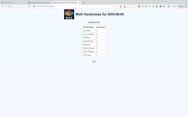
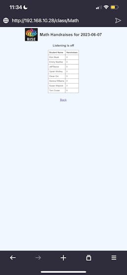
The "class monitor" webpage at 127.0.0.1/class/Math [http://127.0.0.1/class/Math] (for example), shows a continuously updating table of student and number of handraises for that day in that class.
Advantages of the FireBeetle-based Architecture
The FireBeetle 2 ESP32-E microcontroller is a great tool for this task because it allows us to easily transmit the information from sensors like the Pixy2 to the network to be picked up by a computer which can run much more powerful software, connect to the internet or databases, etc. Furthermore, because the system is browser-based, one could easily arrange for the teacher to monitor class participation on his/her/their phone while walking around the classroom. Parents could even check in on their kids' statistics from their phones, if appropriate port forwarding were set up (although, admittedly, that might not be that healthy.)
Future Work
While the current RISE system will facilitate the tracking of student engagement, one shortcoming is that it does not currently allow tracking of WHICH student the teacher actually calls upon. While the teacher could establish a protocol like "whoever I call on, please keep your paddle up", and then the software could be modified to detect the last paddle raised during a question-response event, a better method would be to introduce voice recognition to track and record who a teacher calls upon. In this way, a teacher could proactively eliminate any unconscious bias he or she is imposing whether it be by gender, race, or even classroom positioning.
While the Pixy2 sensor works to implement the RISE system in principle, and is fine for demonstrating proof-of-concept, it is actually more suited to shorter-distance vision tasks, and it can be a bit sensitive to lighting conditions. Ideally, a more robust sensor based on Pixy2 algorithms would be developed for the task of observing colors 15-30 feet away to accommodate larger classrooms.
With higher-resolution cameras and more advanced computer vision, one could also easily imagine eye-tracking installations in a classroom to monitor how much students are paying attention, etc. While there will always be a fine balance between making students feel over-monitored and gathering more student data, we believe that it is only through more data that educational practices can be most effectively improved.
Creating the RISE System:
HARDWARE
The RISE hardware device is quite simple: it is a DFRobot FireBeetle 2 ESP32-E microcontroller connected via I2C serial interface to a CharmedLabs Pixy2 sensor. The reader can construct this same hardware device by following these steps below.
Step 1: Preparing the FireBeetle
Because our device was intended as a prototype, we used a breadboard to make the connections between Pixy2 and FireBeetle. To be able to insert the FireBeetle into a breadboard, we needed to first solder on the header pins (included with FireBeetle).
Once the soldering is complete, simply insert the FireBeetle into the breadboard.
Step 2: Connect the Pixy2 to the FireBeetle
We chose for the FireBeetle ESP32 board to connect to Pixy2 via I2C serial interface. We actually started out trying SPI, but it did not work for us.
The Firebeetle ESP32 board has two I2C pins: one for data (SDA) and one for clock (SCL), and these have to be connected to the corresponding pins on the Pixy2, along with their ground pins. The circuit diagram below shows the connections that must be made.
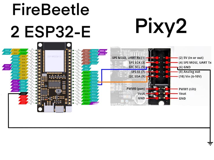
Looking at the back of the Pixy2, you will see a 10-pin socket in the upper right. The pins are numbered as in the circuit diagram above, and you should make the following connections:
- SDA: The data line (SDA) of your Pixy2 sensor on pin 9 should be connected to the SDA pin of your Firebeetle ESP32 board labeled SDA/IO21 (pin 26 using normal anti-clockwise pin-numbering convention).
- SCL: The clock line (SCL) of your Pixy2 sensor on pin 5 should be connected to the SCL pin of your Firebeetle ESP32 board labeled SCL/IO22 (pin 25 in normal pin-numbering convention).
- GND: Finally, you need to connect the ground of both devices; pin 6 on Pixy2 should be connected to the pin labeled GND on the FireBeetle (pin 15 in normal convention).
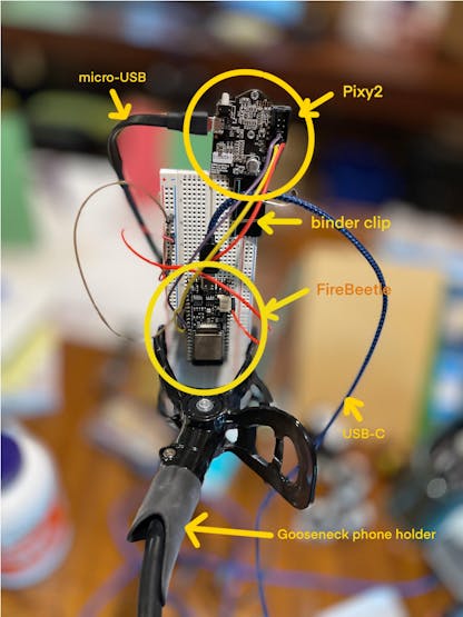
- VCC/Power: Both the Pixy2 sensor and the FireBeetle need power, and we find the most robust method to provide power is to use a standard external phone battery with two USB-A outputs. A USB-A to USB-C cable can be used to connect one of the battery outputs to the USB-C port on the FireBeetle, and a USB-A to micro-USB cable can be used to connect the other battery output to the Pixy2’s micro-USB port.
Step 3: Creating a stand for the device
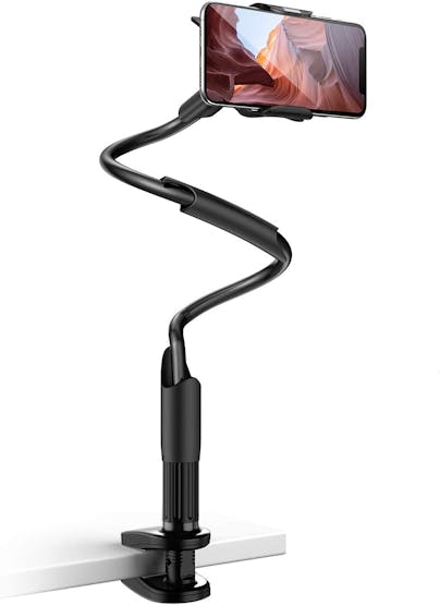
We found it convenient to use either adhesive or a large binder clip to secure the Pixy2 to the top of the breadboard, so that its lens is not obscured by the breadboard, and then used a goosenecked phone holder to act as a flexible holder for the device. See the image "Figure 1: RISE device" and "Figure 2: gooseneck phone holder" below for our setup
Step 4: Setting up the Pixy2
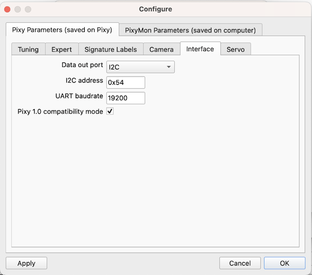
The Pixy2 needs a few key parameters to be set correctly in order to communicate via I2C with the FireBeetle. To do this, you will need to connect the Pixy2 to a computer. To do so, you must plug the USB-A end of the cable connecting the Pixy2 to the Mac or Windows computer instead of the battery. Then you must install and then run PixyMon, a program supplied by the makers of the Pixy2. Once the application is running, and the Pixy2 is plugged into the computer’s USB port, video should appear in the PixyMon window. Click on the gear icon for “Settings”, and go to “Interface”, select “I2C” in the first dropdown and also make sure you have checked the box labeled “Pixy 1.0 compatibility mode”.
Step 5: Upload "RISE_hardware.ino" to FireBeetle
To upload the right code to your FireBeetle using the Arduino Cloud, follow these steps:
- Clone the Github Repository ("joozie75/RISE") referenced in the Project attachments.In the clone directory, find the folder "RISE_hardware_arduino_cloud/", which contains three source files: “RISE_hardware.ino”, "PixyI2C.h", and "TPixy.h".
- Go to your Arduino Cloud WebEditor, and import these three files to a new sketch. - Download the zip file Arduino libraries ESPAsync and AsyncTCP and import them via the Libraries import function in Arduino Cloud WebEditor.
- In the WebEditor, edit line 15 and 16 of "RISE_hardware.ino" to reflect the SSID and password of your wifi network.
- In the WebEditor, edit lines 23-25 of "RISE_hardware.ino" to reflect the IP address the FireBeetle should publish its detections to. This IP address should be accessible from the wifi network (typically, something like 192.168.1.99).
- Finally, in the Arduino Cloud WebEditor, select the "FireBeetle-ESP32" board as hardware, connect the Firebeetle via USB-C, and upload the sketch to the FireBeetle by clicking the Upload arrow button.
Alternatively, you can use the Arduino IDE on your local computer by following the instructions given here: If you go this route, please note the following:
- Use the Github Repo folder "RISE_hardware_arduino_ide/", which contains only one source file for the sketch, "RISE_hardware.ino".
- At the time of writing, we received an error in this step: “Open Arduino IDE, File->Preferences, find Additional Boards Manager URLs, copy the below link, and paste in the blank. Instead, we had to download that json file to the local computer and put in “file://
- Include the ESPAsync, AsyncTCP, and Pixy2 libraries via “Sketch->Include Library->Add.ZIP Library…”.
- Select hardware device as "FireBeetle ESP32-E", connect the FireBeetle via USB-C, and compile and upload the sketch.
Step 6: Test the RISE Hardware
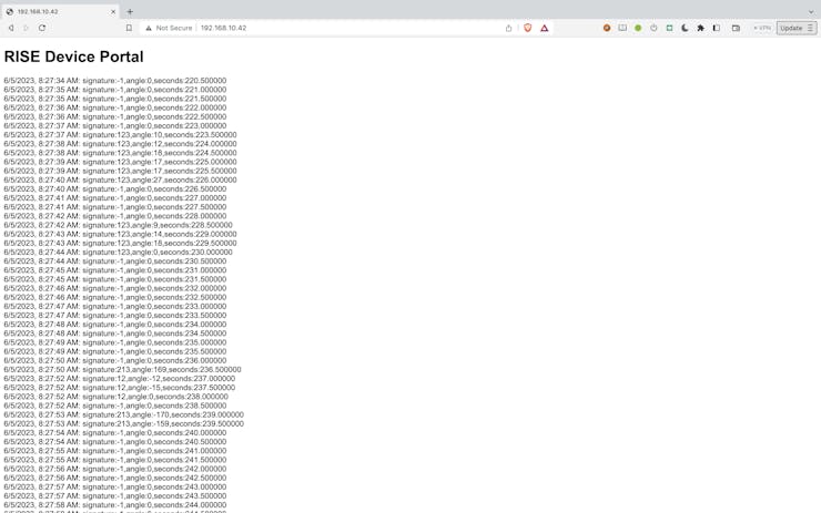
Once the "RISE_hardware.ino" code has been uploaded to the FireBeetle, connect the Pixy2 to battery power or computer power via micro-USB, and then open a browser and navigate to the IP address you designated in the.ino file. For us, that means we go to http://192.168.10.42:80 [http://192.168.10.42/]. If it is working, you should see “RISE Device Portal”, and then periodic printouts of “signature, angle, second” tuples, as in the figure below.
Step 7: Make Cardboard Paddles
Choosing Colors
In order for Pixy2 to distinguish the color signatures of students, we have to make the colored paddles and then train Pixy2 on the colors. We would recommend choosing 4 or 5 distinct colors, depending on how many students you need to distinguish. Choosing 5 colors would allow for 50 signatures, while 4 colors would allow for 24 signatures. Generally, choosing N colors should allow for 2x(N choose 2) + 3x(N choose 3) signatures involving 3 colors. With 5 colors, a signature might look like (3, 4, 3), meaning that from left to right on the paddle, the colors would be the colors designated color 3, color 4, then color 3. We would not allow both signatures (1, 3, 4) and (4, 3, 1) as the Pixy2 registers these as the same signature at different angles.
Construction
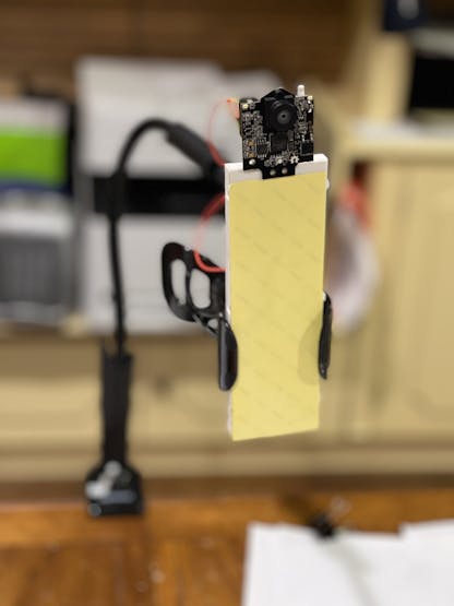
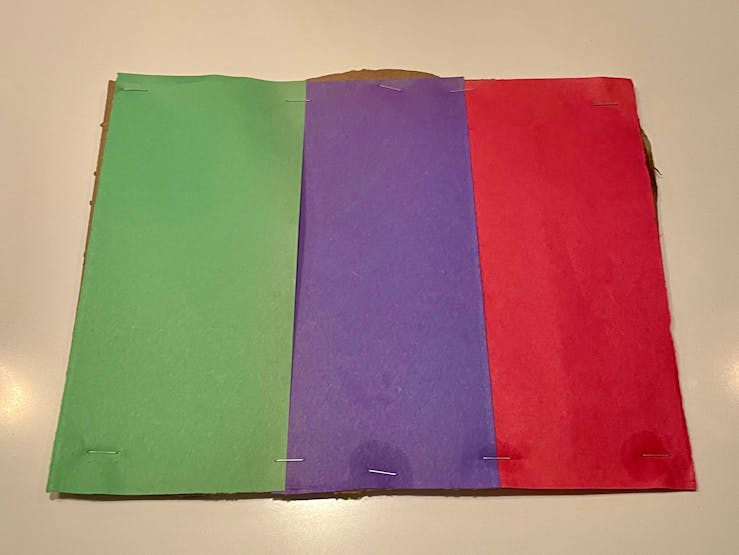
The paddles will be the shape and size of an 8 1/2" by 11" sheet of paper. For stiffness, they will be made out of one layer of cardboard under a layer of different colors of colored construction paper. The long side of the cardboard will be divided into three approximately equal sections; each section will be entirely covered by a piece of construction paper, leading it to look like the German or French flag. For example, the figure below shows a completed paddle:
It could also be like the Canadian flag (without the maple leaf), because it is allowable to have only 2 colors, as long as adjacent colors are distinct.
To create the paddles, begin by gathering the right materials: cardboard, colored construction paper, and staples. Start by cutting out an 8.5" x 11" rectangle from the cardboard. Next, cut 3 rectangles about 1/3 the size of the cardboard, which will serve as the colored sections on the paddles. Arrange the colored rectangles on the cardboard in the order dictated by the paddle's color signature. To secure the colored rectangles, use a stapler to attach them around the edges, all construction paper must slightly overlap, because the camera looks for colors that are next to each other without gaps. Trim any excess material. Finally, use glue or staples to attach a popsicle stick or paint stirrer to create a convenient handle.
Step 8: Tell Pixy2 the Colors
Next, you need to tell Pixy2 about the set of colors you will be using for the paddles. The Pixy2 has to be told, through a computer running PixyMon, which colors correspond to which signature number. Do the following steps:
- In Pixymon, do “Action->Clear All Signatures”
- Present a cardboard paddle containing color 1 in front of the Pixy2, and then select “Action->Set CC Signature 1”. This will freeze-frame the video; then use your mouse to select a portion of the image that contains only color 1.
- step 2 for the N colors you are using in all your cardboard paddles.
Step 9: Run the Python server code on computer
To run the python web server on your computer, do the following:
On the computer, on which you will be running the web server, install Python.Clone the Github repo "joozie75/RISE" into a directory. From the directory containing the downloaded file "setup.py", run "pip install." (note the period at the end of that command). Run the command"python -m RISE_server.server --dbname school.db --device_ip 192.168.10.42", where you should use the IP address you specified in the.ino file you uploaded to the FireBeetle from Arduino Cloud or IDE. If the database file "school.db" does not already exist, then it will be created with the required tables.
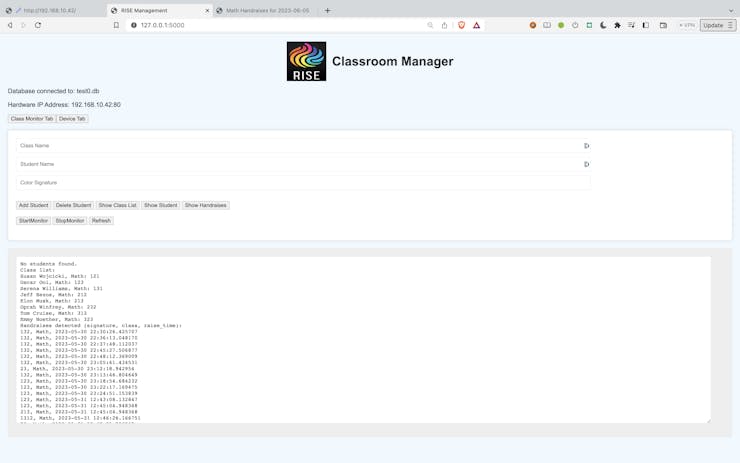
After these steps, if you navigate to http://127.0.0.1:5000 on any web browser, the webpage in the figure below should appear.
Step 10: Start Using the RISESystem
Add students to the database using the RISEweb interface
Now that all the pieces of the system have been prepared, you are ready to use the system. Start by assigning each student a color signature corresponding to the paddle they will be using. The signature "325" means, from left to right on the paddle: color 3, color 2, and then color 5.
From the RISE webpage, you should add students and their signatures to each class using the appropriate text input boxes and buttons. Each (student, class, signature) tuple will be recorded into the class_students table of the database.
Power on the RISE hardware and position Pixy2
Provide power to your RISE hardware by plugging the USB-A plugs into a battery, and mount your device stand in a place where the students can be seen.
Start Monitoring the Hand Raises in your Class
On the RISE webpage, click "Start Monitor" followed by "Class Monitor Tab", which will take you to a webpage like in the figure below, showing a table of handRaises for each student in today's class, which will update in real time every 3 seconds.
Schematics
- FireBeetle 2 ESP32-E connections to Pixy2
Code
- PixyI2C.h(C/C++)
- Python webserver: server.py(Python)
- HTML for Python webserver: index.html(HTML)
- Main Arduino Code: RISE_hardware.ino(C/C++)
- TPixy.h(C/C++)
- Python webserver auxiliary file: participationater.py(Python)
- HTML for Python webserver: index.html(HTML)
- HTML for Python webserver: classtable.html(HTML)
Recommended way to get code: Github repo to RISE
The article was first published in Hackster, June 7, 2023
cr: https://www.hackster.io/the-ardoois/rise-recorder-of-individual-student-engagement-17f850
author: Team The Ardoois: James Ooi, Benji Ooi, Oscar Ooi, Matthew McGowan


