


The Unihiker Smart Home is a home automation system capable of controlling various home appliances in the home it is also coupled with a Door Cam based on an M5 stack ESP32 camera which takes pictures and sends them to the unihiker whenever a visitor rings your doorbell.
The Smart Home system is comprised of the following key parts:
Door Cam: A doorbell camera that captures an image when the button is pressed and sends it to the homeowner.
Relay Controller: A device for managing various home appliances and electronics, such as light bulbs and fans.
UniHiker: Serves as the smart home hub. It runs a flask server in which the other two devices the Door Cam and the Relay Controller communicate with.
The relay controller is made of 8 relays that are controlled by an ESP32 controller. The ESP32 receives commands from the unihiker via HTTP request and based on the command turns on a particular relay, which in turn drives an AC load. For the relay controller, I used a 16-channel relay shield but only used 8 relays.
The connection between the relay shield and the esp32 is expressed in the image below.

The code
The code for the relay controller is fairly simple. You can find the code in my GitHub repository in the directory ESP32_Relay_Controller.

The ESP32 used here is the ESP32 Wroom Devkit, so when uploading your code select ESP32 Wroom as your board when uploading code using the Arduino IDE.
The UniHiker serves as the hub of the Smart Home system, running a Flask server that manages the entire setup. Each device within the system either receives commands from or sends data to the UniHiker. The Smart Home system is built on a server-client architecture, with the UniHiker functioning as the central server and all connected devices, like the Door Cam and relay controller, operating as clients. These clients communicate with the UniHiker via Wi-Fi.

The Code
The code performs three key functions:
- It runs a Flask server.
- Receives images from the Door Cam.
- Sends commands to the Relay Controller.
First, we import all libraries

Next, we initialize the UniHiker board, enabling the use of its IO pins. We also instantiate the UniHiker GUI class, which will be essential for creating buttons in the interface.

The Relay Controller is managed by an ESP32, which receives commands from the UniHiker. For this setup to work, the UniHiker needs to be aware of the IP address of the ESP32 and the specific route (`/pin`) where commands should be sent. Make sure to replace the IP address in the code with the IP address of your ESP32.

To create a button, I used an image with an `onclick` event. However, I needed to store information about the button's state—whether it is on or off—as well as its position, name, and other relevant details. To manage this, I created a data class called `Button`.built-in

When the button is pressed, the image of the button changes depending on its previous state and a request is sent to the relay controller. The function below handles this functionality.

Whenever an image is sent via the Door Cam, the built-in buzzer in the UniHiker emits a sound. To achieve this, we must create a tone object using the buzzer pin `Pin.P26` and set the tone frequency we want to play.

As mentioned earlier, the buttons are represented as images. To display them, we need to create an object of the `Button` data class that we made. This data class is also responsible for drawing the button's image using the `gui.draw_image()` function.

Next, we need to reserve space for displaying the image sent by the Door Cam. We'll do this by placing a sample image in the designated area. When an image arrives from the Door Cam, it will replace the sample image.

Then, we create a flask app

When the Door Cam sends an image to the unihiker, it is stored in a folder called upload. We create this folder via the code below:

To upload an image to the Unihiker via the Flask server, we will create a form that allows us to upload a file. This is done via the code below:

The ESP32 Door Cam will take advantage of this form when uploading images. Pay attention to the `name` attribute in the input tag, which is set to 'file'. This name must also match the corresponding variable in the ESP32 Door Cam code. While I've already set this up, be sure to maintain this consistency if you plan to modify the code.
The remainder of the code handles receiving the image from the Door Cam, displaying it on the screen, and sounding the buzzer as a notification. You can find the full code in my GitHub repository here.
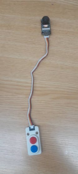
The Door Cam is a doorbell with a camera, I used the M5 stack ESP32 Camera and M5 stack dual button unit. Whenever the red button is pressed an Image is taken and sent to the unihiker display to be seen by the user who is notified by Unihiker's in-built buzzer. To build this, connect the dual button to the HY2.0-4P i2c port of the ESP32 camera. Do note that the buttons do not use I2C we are just using the I2C pins as input pins for our button.

Adding an Indicator LED
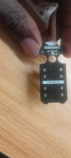
The M5stack esp32 camera does not have external GPIOs so we will hack the M5 dual button and use one of the button's GPIO as our LED.
- First, open the M5 stack dual-button.
- Attach a 270 ohms resistor to the anode of the LED

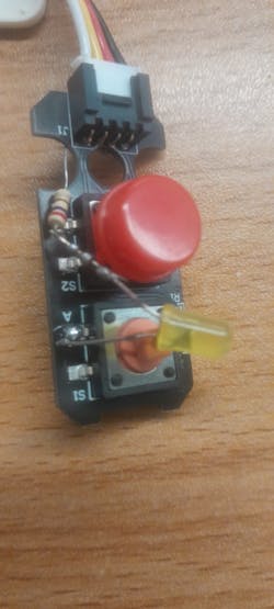
solder the cathode to the pin labelled A on the button's PCB and the solder anode to the pin labelled 5 behind the PCB
How to setup
By now you should have downloaded or cloned the GitHub repository for this project, open the folder Door cam.


upload the DoorCam.ino [http://doorcam.ino/] file to the camera. Do note the board type is M5unitCAM

Before uploading the code, update the following variables:

When the code has uploaded, open the serial monitor and set its baud rate to 115200 you should see a message similar to this:


This above output will show on the serial monitor if the esp32 has no previously saved network or failed to connect to one, then a web portal will be created at the IP address shown on the screen.
open your phone or PC wifi setting and connect to WiFi network named Door-cam.

immediately you are connected to the device your browser should automatically pop up and open the web address if it doesn't, type in the IP address on the serial monitor in your browser. You should see the screen below:

click on Configure WiFi, select your router, input its password and click Save.

When connected you should see the image below on your serial monitor

Immediately the camera will start trying to initialize a connection with the server.

The server here is the Unihiker running a flask server. The unihiker has to be on, connected to the same WiFi network as the camera and currently running the server otherwise the camera won't be able to initialize a connection to it.
Press the red button, and you should see the following on the serial monitor:

You should also see an image appear on the unihiker screen

Debugging Camera Issues
If the LED is not coming on, it means there is an issue connecting with the server. it could be one of the following:
- The camera is not on the same wifi network as the server.
- The server is not running.
- The router that is used to create the network is not ON or not available
- The camera is having issues connecting to the router.
If the LED is on and images are not sent to the unihiker; then, there is an issue with the camera. The issue could be any of the following:
- You are not using the same camera model as me. If you do plan to use a different ESP32 camera model, go to Arduino Examples > ESP32 > Camera. You should see all board models in the CameraWebServer.ino file

go to camera_pins.h and copy the pins for your camera model

and replace it with the pins in the Door cam.ino code

- if you used the same camera as me, you probably chose the wrong board in board options. The board should be M5unitcam
Due to the DHCP server on my router, IP addresses change occasionally and are only reserved for a fixed period, so whenever the IP address changes the codes have to be updated.
To remedy this you can enable Static IP configurations on your router. To do this you would need the MAC address of each of the devices in our smart home system that are connected to the router.

IP addresses for connected devices are created based on some other factors, but we can skip that, by just assigning the same IP address that was initially assigned via DHCP.

Your router UI would probably be different than mine. You just have to go through the various options in your router to find static IP, then you just need to input the device MAC address and then the static IP you want it to have.
In our setup, all devices are connected to our router, so we can easily view their MAC addresses directly from the router's dashboard. Log in to your router dashboard and navigate to the section where all connected devices are listed. There, you should be able to see the MAC addresses of all the connected devices.

Another method to obtain the MAC address of the devices, specifically for the ESP32s (including the camera and the relay controller), is by uploading the following code from random nerd tutorials:


