GPS Time & Internet Time As a Backup Using Visuino

In this Visuino project, ensure accurate timekeeping with a dual-source system! The ESP8266-D1 Arduino-compatible board retrieves time from the NEO-6M GPS module. If the GPS signal is lost, the board automatically switches to Wi-Fi and fetches the accurate date and time from an NTP server. This makes it a perfect backup solution for real-time applications!


Watch the video!

Big thanks to Stephan Buth for this great project idea! Check out his Youtube channel!

STEP 1
What You Will Need

What You Will Need

What You Will Need

What You Will Need

What You Will Need

What You Will Need

What You Will Need

ESP8266-D1 Arduino Compatible Development Board (Or any other board with WiFi)NEO-6M GPS Breakout Module with AntennaBreadboardLCD I2C 16X2Jumper wiresVisuino software: Download here
STEP 2
The Circuit

The Circuit

Connect LCD pin [SCL] to ESP8266-D1 pin [SCL]Connect LCD Sensor pin [SDA] to ESP8266-D1 pin [SDA]Connect LCD Sensor pin [VCC] to ESP8266-D1 pin [5v]Connect LCD Sensor pin [GND] to ESP8266-D1 pin [GND]


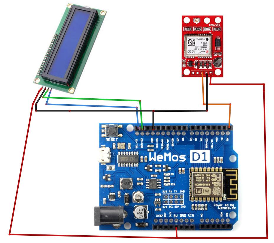
Connect NEO-6M GPS module pin [VCC] to ESP8266-D1 pin [5v]Connect NEO-6M GPS module pin [GND] to ESP8266-D1pin [GND]Connect NEO-6M GPS module pin [TX] to ESP8266-D1 pin [RX]
STEP 3
Start Visuino, and Select the WeMos D1 / R2 Board Type

Start Visuino, and Select the WeMos D1 / R2 Board Type

Start Visuino, and Select the WeMos D1 / R2 Board Type

The Visuino: https://www.visuino.com also needs to be installed. Download Free version or register for a Free Trial.

Start Visuino as shown in the first picture Click on the "Tools" button on the Arduino component (Picture 1) in Visuino When the dialog appears, select "WeMos D1 / R2" as shown on Picture 2

STEP 4
WiFi Setup

WiFi Setup

WiFi Setup

WiFi Setup

WiFi Setup

WiFi Setup

WiFi Setup

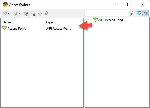
Select WeMos D1 / R2 board and in the editor Modules>WiFi>Access Points, click on [...] button, so that "Access points " window will open.In this editor drag the WiFi access point to the left side.

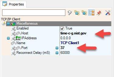
In the properties window Under "SSID" put the name of your WiFi NetworkUnder "Password" put the access password for your WiFi networkClose the "Access points" windowOn the left in editor select Modules>Wifi>Sockets, click on [...] button, so that "Sockets" window will open Drag the TCP/IP Client from right to the left side, then Under Properties window set port: 37 and host: time-c-g.nist.govClose the "Sockets" window
STEP 5
In Visuino Add & Set Components

In Visuino Add & Set Components

In Visuino Add & Set Components

In Visuino Add & Set Components

In Visuino Add & Set Components

In Visuino Add & Set Components

In Visuino Add & Set Components

In Visuino Add & Set Components

In Visuino Add & Set Components

In Visuino Add & Set Components

In Visuino Add & Set Components

In Visuino Add & Set Components

In Visuino Add & Set Components

In Visuino Add & Set Components

In Visuino Add & Set Components

In Visuino Add & Set Components

In Visuino Add & Set Components

In Visuino Add & Set Components

Add "Liquid Crystal Display (LCD) - I2C" componentDouble click on the "LiquidCrystalDisplay1" and in the Elements window drag "Text Field" to the left sideIn the Elements window drag another "Text Field" to the left side and in the properties window set "Row" to 1, "Initial Value" to ------Close the Elements window


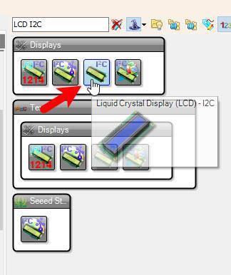
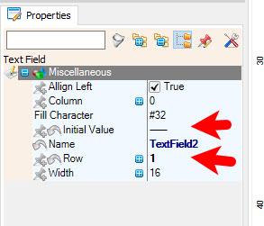
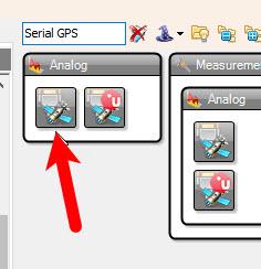
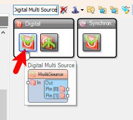
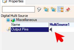
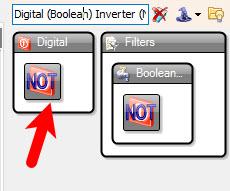
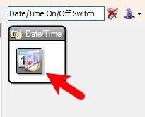
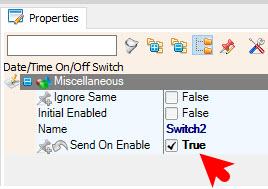
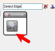
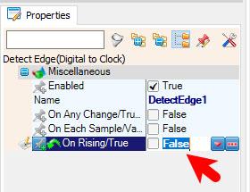
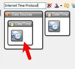
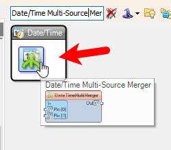
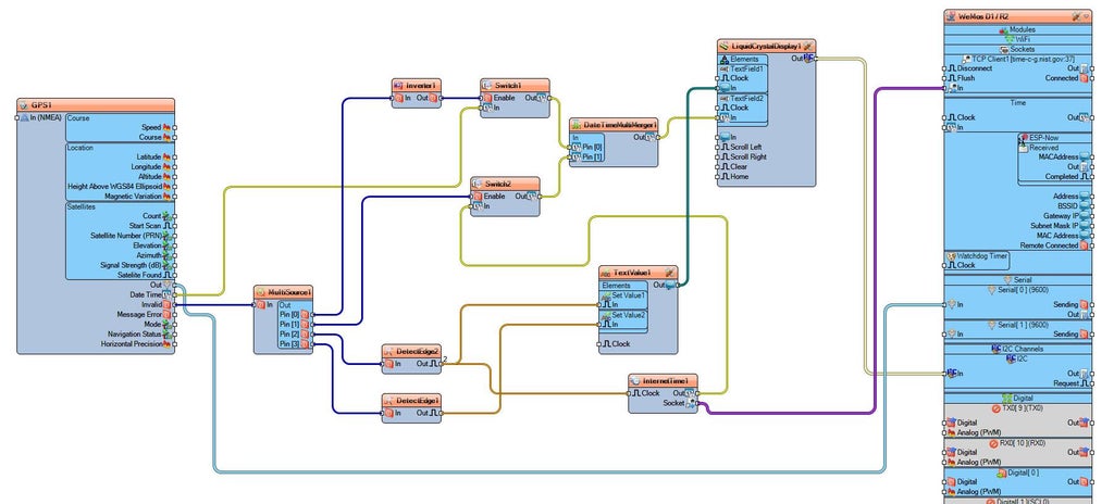
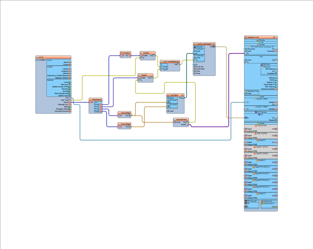
Add "Serial GPS" componentAdd "Digital Multi Source" component, and in the properties window set "Output Pins" to 4Add "Digital (Boolean) Inverter (Not)" componentAdd 2X "Date/Time On/Off Switch" component and for both in the properties window set "Send On Enable" to TrueAdd 2X "Detect Edge(Digital to Clock)" component and for the first one in the properties window set "On Rising/True" to FalseAdd "Internet Time Protocol" componentAdd "Date/Time Multi-Source Merger" componentAdd "Text Value" componentDouble click on "TextValue1" and in the Elements window drag "Set Value" to the left side and in the properties window set "Value" to Internet Timedrag another "Set Value" to the left side and in the properties window set "Value" to GPS TimeClose the Elements window
STEP 6
In Visuino Connect Components
Connect "GPS1" pin [Out] to WeMos D1 / R2 Serial [0] pin [In]Connect "GPS1" pin [Date Time] to "Switch1" pin [In]Connect "GPS1" pin [Invalid] to "MultiSource1" pin [In]Connect "MultiSource1" pin [0] to "Inverter1" pin [In]Connect "MultiSource1" pin [1] to "Switch2" pin [Enable]Connect "MultiSource1" pin [2] to "DetectEdge1" pin [In]Connect "MultiSource1" pin [3] to "DetectEdge2" pin [In]Connect "Inverter1" pin [Out] to "Switch1" pin [Enable]Connect "Switch1" pin [Out] to "DateTimeMultiMerger1" pin [0]Connect "Switch2" pin [Out] to "DateTimeMultiMerger1" pin [1]Connect "DetectEdge1" pin [Out] to "TextValue1" > "Set Value2" pin [In]Connect "DetectEdge2" pin [Out] to "TextValue1" > "Set Value1" pin [In]Connect "DetectEdge2" pin [Out] to "InternetTime1" pin [Clock]Connect "InternetTime1" pin [Out] to "Switch2" pin [In]Connect "InternetTime1" pin [Socket] to "WeMos D1 / R2" >TCP Client1 pin [In]Connect "DateTimeMultiMerger1" pin [Out] to "LiquidCrystalDisplay1" > "Text Field2" pin [In]Connect "TextValue1" pin [Out] to "LiquidCrystalDisplay1" > "Text Field2" pin [In]Connect "LiquidCrystalDisplay1" pin I2C Control to "WeMos D1 / R2" I2C In
STEP 7
Generate, Compile, and Upload the Code

Before Upload, disconnect pin RX on the board and after the Uploading connect it back.

In Visuino, at the bottom click on the "Build" Tab, make sure the correct port is selected, then click on the "Compile/Build and Upload" button.

STEP 8
Play

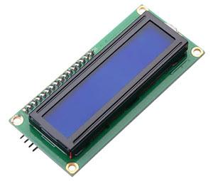
If you power the ESP board, the LCD will start to show the GPS Date & Time, if the GPS Signal is lost it will connect to the Internet time server and get the current Date & Time.

Congratulations! You have completed your project with Visuino. Also attached is the Visuino project, that I created for this Instructable, you can download it and open it in Visuino: https://www.visuino.com

icon GPS-INT-BACKUP-TIME.zip 2KB Download(0)
License
All Rights
Reserved
licensBg
0