Display Time on M5Stack CoreS3 ESP32-S3

Display Time on M5Stack CoreS3 ESP32-S3

In this project you can learn how to use Visuino to display time on the M5Stack CoreS3 using internal RTC module.

This project was made by Visuino user Rafał. Visit his youtube channel here: https://www.youtube.com/@Edappl/videos

STEP 1
What You Will Need
STEP 2
Start Visuino, and Select the M5 Stack CoreS3 Board Type

Start Visuino, and Select the M5 Stack CoreS3 Board Type

Start Visuino, and Select the M5 Stack CoreS3 Board Type

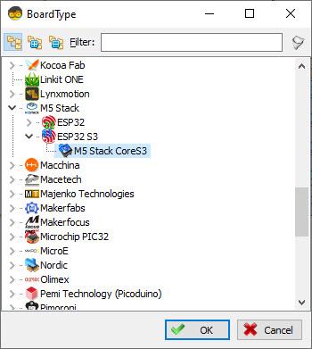
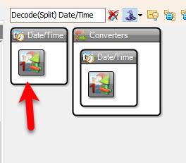
Start Visuino as shown in the first picture Click on the "Tools" button on the Arduino component (Picture 1) in Visuino When the dialog appears, select "M5 Stack CoreS3" as shown on Picture 2

STEP 3
In Visuino Add & Set Components

In Visuino Add & Set Components

In Visuino Add & Set Components

In Visuino Add & Set Components

In Visuino Add & Set Components

Add "Decode(Split) Date/Time" componentAdd "Formatted Text" component

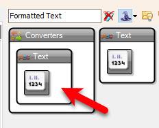
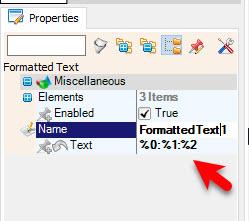
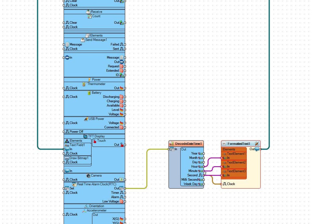
Double click on the "FormattedText1" and in the Elements window drag 3X "Text Element" to the left side and close the Elements windowSelect "FormattedText1" and in the properties window set "Text" to: %0:%1:%2

(Where %0 represents TextElement1, %1 represents TextElement2, %2 represents TextElement3)

STEP 4
In Visuino Set M5 Stack CoreS3 Display

In Visuino Set M5 Stack CoreS3 Display

In Visuino Set M5 Stack CoreS3 Display

In Visuino Set M5 Stack CoreS3 Display

In Visuino Set M5 Stack CoreS3 Display

In Visuino Set M5 Stack CoreS3 Display

In Visuino Set M5 Stack CoreS3 Display

Select "M5 Stack CoreS3" board and in the properties window expand "Modules">"TFT Display">"Elements" and click on the 3 dots buttonIn the "Elements" window drag "Text Field" to the left sideIn the "Elements" window drag 6X "Draw Scene" to the left side, and in the properties window set "Color" to $FF0080FF ,"Fill Color" to aclBlack, "Size" to 6, "Width" to 20, "X" to 20, "Y" to 10In the "Elements" window drag "Draw Bitmap" to the left side, and in the properties window set "X" to 50, "Y" to 90, Select "Bitmap" and click on the 3 dot button and in the Bitmap Editor Load the bitmap that is attached above (the Bell)Close All the windows
STEP 5
In Visuino Connect Components
Connect M5 Stack CoreS3>Real Time Alarm Clock(RTC) pin [Out] to "DecodeDateTime1" pin [In]Connect "DecodeDateTime1" pin [Hour] to "FormattedText1" > "TextElement1" pin [In]Connect "DecodeDateTime1" pin [Minute] to "FormattedText1" > "TextElement2" pin [In]Connect "DecodeDateTime1" pin [Second] to "FormattedText1" > "TextElement3" pin [In]Connect "DecodeDateTime1" pin [Second] to "FormattedText1" pin [Clock]Connect "FormattedText1" pin [Out] to M5 Stack CoreS3>TFT Display>Text Field1 pin [In]
STEP 6
Generate, Compile, and Upload the Code

Generate, Compile, and Upload the Code

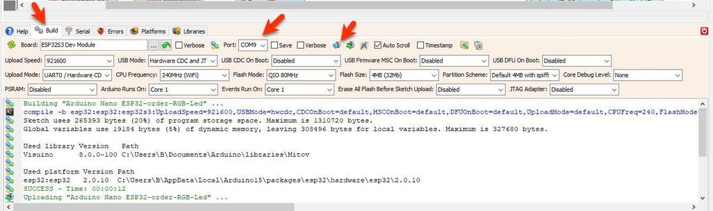
In Visuino, at the bottom click on the "Build" Tab, make sure the correct port is selected, then click on the "Compile/Build and Upload" button.

STEP 7
Play

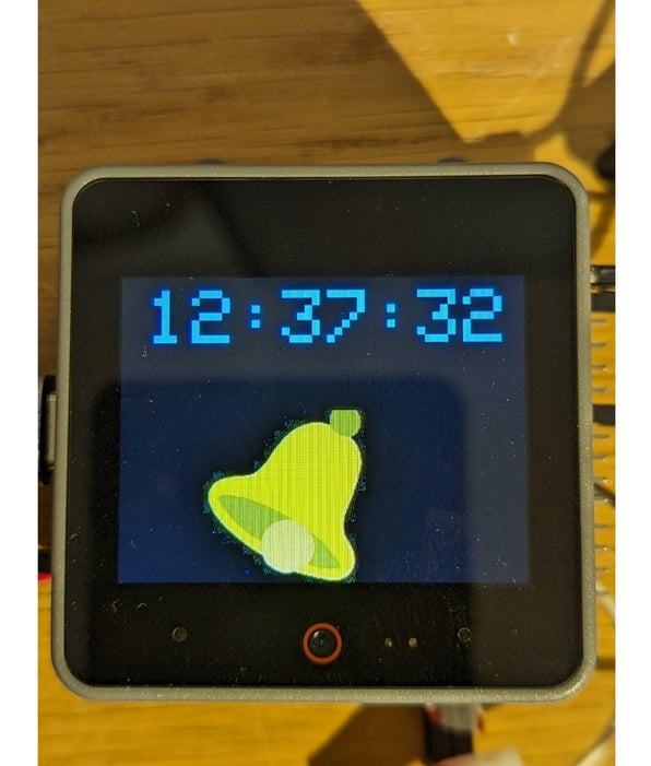
After uploading the project to the M5 Stack CoreS3 the board will start to display Time.

Congratulations! You have completed your LED project with Visuino. Also attached is the Visuino project, that was created for this Tutorial. You can download and open it in Visuino: https://www.visuino.com

icon clock+m5+stack-s3.zip 30KB Download(0)
License
All Rights
Reserved
licensBg
0