LED Matrix Countdown Timer Using Visuino

In this tutorial we are going to build a simple Countdown timer using LED Matrix MAX7219 and Arduino.

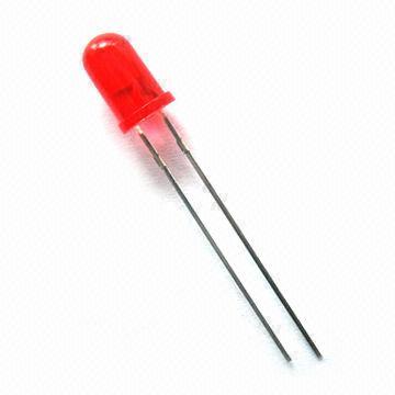
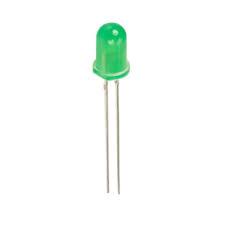
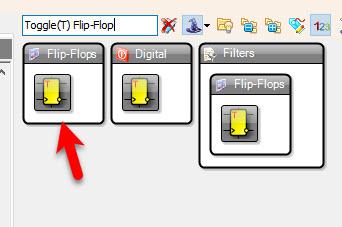
By pressing on the button you can the Green LED will glow and the timer will countdown from 9 yo 0, once the 0 is reached a Red LED will glow. You can replace the LED with a relay or any other module.

Watch the Video!

STEP 1
What You Will Need

What You Will Need

What You Will Need

What You Will Need

What You Will Need

What You Will Need

What You Will Need

What You Will Need

What You Will Need

What You Will Need

Arduino (or any other board)8X8 LED Matrix MAX7219Button3X 1K ohm resistorGreen LEDRed LEDBreadboardJumper wiresVisuino program: Download Visuino
STEP 2
The Circuit

The Circuit

Connect Arduino pin [5V] to breadboard positive pin [Red line]Connect Arduino pin [GND] to breadboard negative pin [Black line]Connect Arduino Digital pin [7] to the Resistor2Connect other side of the resistor2 to the Red LED positive pinConnect Red LED negative pin to breadboard pin [GND]Connect Arduino Digital pin [6] to the Resistor1Connect other side of the resistor1 to the Red LED positive pinConnect Red LED negative pin to breadboard pin [GND]Connect Arduino Digital pin [2] to button on the breadboard and to the Resistor3Connect other side of the resistor3 to the breadboard pin [GND]Connect Other pin of the button to the breadboard positive pin [5V]


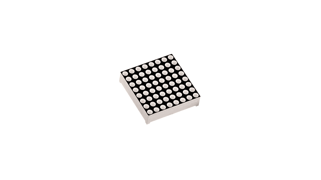
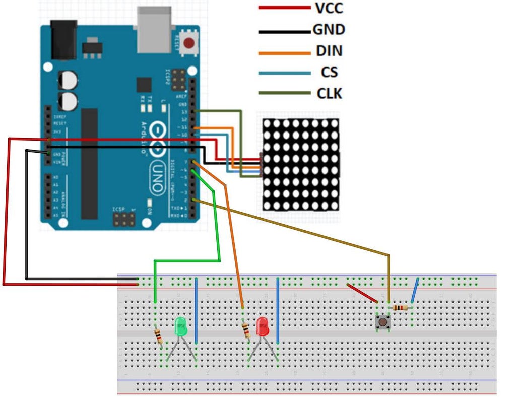
Connect LED Matrix pin[VCC] to Arduino pin[5V]Connect LED Matrix pin[GND] to Arduino pin[GND]Connect LED Matrix pin[DIN] to Arduino digital pin[11]Connect LED Matrix pin[CS] to Arduino digital pin[10]Connect LED Matrix pin[CLK] to Arduino digital pin[13]
STEP 3
Start Visuino, and Select the Arduino Board Type

Start Visuino, and Select the Arduino Board Type

Start Visuino, and Select the Arduino Board Type

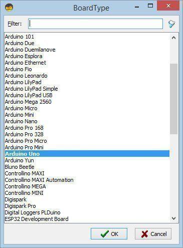
Start Visuino as shown in the first picture Click on the "Tools" button on the Arduino component (Picture 1) in Visuino When the dialog appears, select "Arduino UNO" as shown on Picture 2 or any other board.

STEP 4
In Visuino Add Components

In Visuino Add Components

In Visuino Add Components

In Visuino Add Components

In Visuino Add Components

In Visuino Add Components

In Visuino Add Components

In Visuino Add Components

In Visuino Add Components

Add "Debounce Button" componentAdd "Toggle(T) Flip-Flop" componentAdd "Pulse Generator" componentAdd "Up/Down Counter" componentAdd "Digital Multi Source" componentAdd "Integer Multi Source" componentAdd "Digital (Boolean) Inverter (Not)" componentAdd "Maxim LED Display Controller SPI MAX7219/MAX7221" component
STEP 5
In Visuino Set Components

In Visuino Set Components

In Visuino Set Components

In Visuino Set Components

In Visuino Set Components

In Visuino Set Components

In Visuino Set Components

In Visuino Set Components

Select "PulseGenerator1" and in the properties window select "Enabled" and set it to False, click on the pin icon and select "Boolean SinkPin"

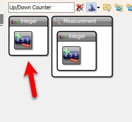
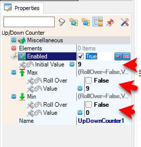
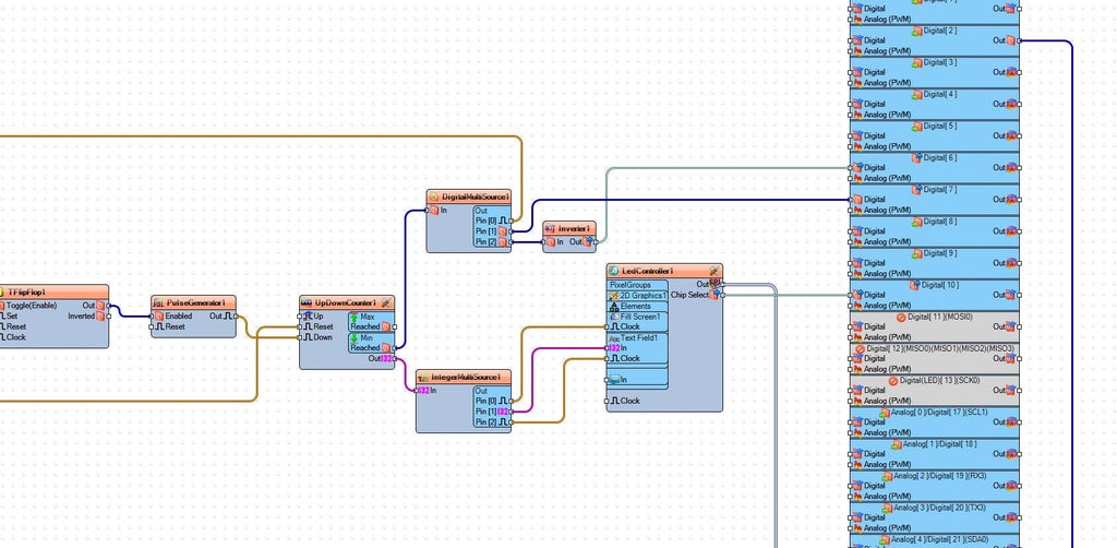
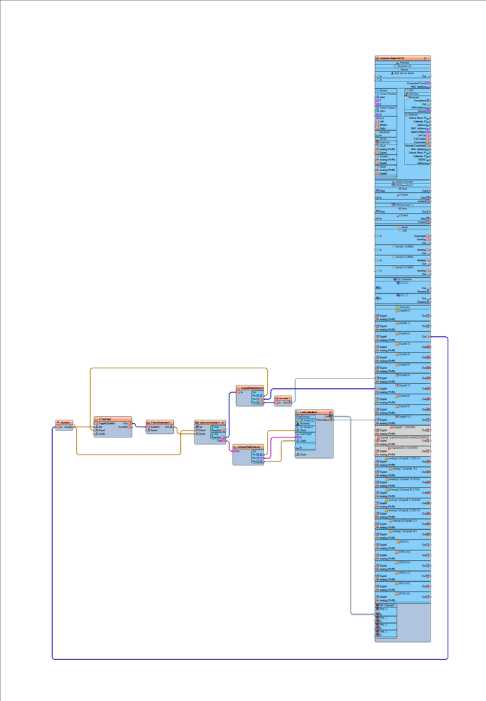
Select "UpDownCounter1" and in the properties window set:

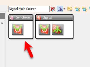
Initial Value to 9Max > Roll Over to FalseMax > Value to 9Min > Roll Over to FalseMin > Value to 9

Select "DigitalMultiSource1" and in the properties window set "Output Pins" to 3

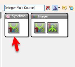
Select "IntegerMultiSource1" and in the properties window set "Output Pins" to 3

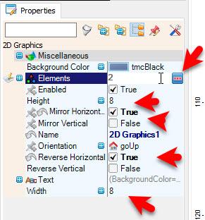
Double click on the "LedController1" and in the "Pixel Groups" window drag "2D Graphics" to the left sideand in the properties window set "Mirror Horizontal" to True and "Reverse Horizontal" to True and set "Width" to 8 and "Height" to 8also select "Elements" in the properties window and click on the 3 dots button

In the Elements window drag:

"Fill Screen" to the left side"Text Field" to the left side and in the properties window set "Wrap" to FalseClose the "Elements" WindowClose the "Pixel Groups" window
STEP 6
In Visuino Connect Components
Connect Arduino digital pin [2] to "Button1" pin [In]Connect "Button1" pin [Out] to "TFlipFlop1" pin [Clock]Connect "Button1" pin [Out] to "UpDownCounter1" pin [Reset]Connect "TFlipFlop1 pin [Out] to "PulseGenerator1" digital pin [Enabled]Connect "PulseGenerator1" pin [Out] to "UpDownCounter1" pin [Down]Connect "UpDownCounter1" pin [Min Reached] to "DigitalMultiSource1" pin [In]Connect "UpDownCounter1" pin [Out] to "IntegerMultiSource1" pin [In]Connect "DigitalMultiSource1" pin [0] to "TFlipFlop1" pin [Reset]Connect "DigitalMultiSource1" pin [1] to Arduino digital pin [7]Connect "DigitalMultiSource1" pin [2] to "Inverter1" pin [In]Connect "Inverter1" pin [Out] to Arduino digital pin [6]Connect "IntegerMultiSource1" pin [0] to "LedController1" > "Fill Screen1" pin [Clock]Connect "IntegerMultiSource1" pin [1] to "LedController1" > "Text Field1" pin [In]Connect "IntegerMultiSource1" pin [1] to "LedController1" > "Text Field1" pin [Clock]Connect "LedController1" Pin Out SPI to Arduino Board pin SPI InConnect "LedController1" Pin Chip Select to Arduino Board Digital pin [10]
STEP 7
Generate, Compile, and Upload the Arduino Code

Generate, Compile, and Upload the Arduino Code

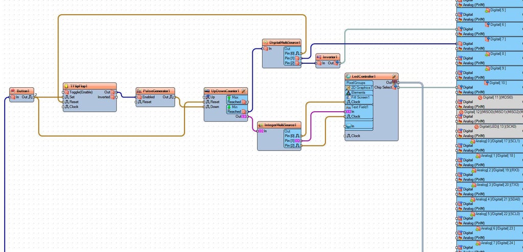
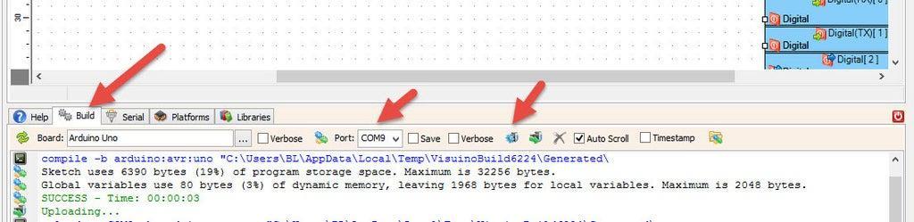
In Visuino, at the bottom click on the "Build" Tab, make sure the correct port is selected, then click on the "Compile/Build and Upload" button.

STEP 8
Play

If you power the Arduino board, the LED Matrix will show the countdown time, if you press the button you will be able to reset the time. When the countdown is active a Green LED will glow, once the countdown is finished a Red LED will glow.

Congratulations! You have completed your project with Visuino. Also attached is the Visuino project, that I created for this tutorial, you can download it and open it in Visuino: https://www.visuino.eu

icon nano-ledmatrix-count.zip 2KB Download(0)
License
All Rights
Reserved
licensBg
0