Arduino Buzzer & LED Siren With 4x1 Keypad Using Visual Programming

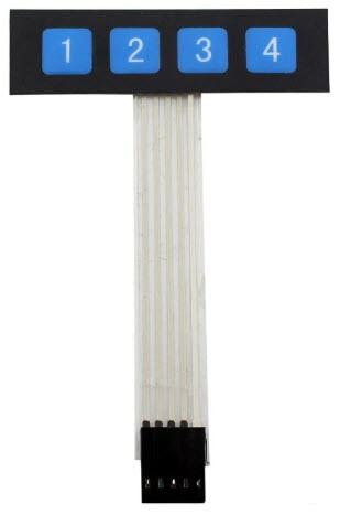
In this Visuino tutorial, we’ll build a fun project using an Arduino, a buzzer with red LED module (connected to pin 6 PWM), and a 4x1 membrane keypad. Each keypad button will trigger a different analog waveform generator to produce unique siren sounds, while the LED glows accordingly:
Key 1: Square wave sirenKey 2: Sine wave sirenKey 3: Triangle wave sirenKey 4: Gauss wave sirenThis project demonstrates how easy it is to combine sound and light effects with keypad input using Arduino and Visual Programming in Visuino.
Watch the video!
Step 1: What You Will Need


Step 2: The Circuit

Step 3: Start Visuino, and Select the Arduino Board Type

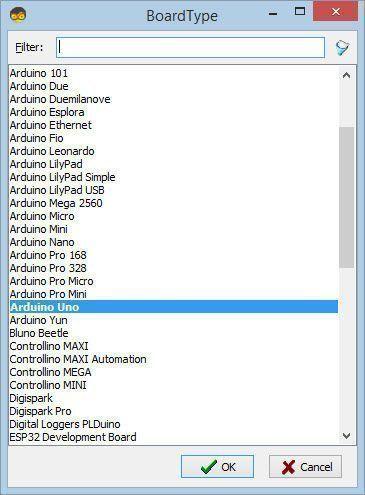
Start Visuino as shown in the first picture Click on the "Tools" button on the Arduino component (Picture 1) in Visuino When the dialog appears, select "Arduino UNO" as shown on Picture 2
Step 4: In Visuino Add & Set Components
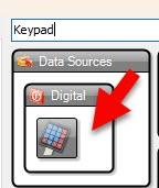
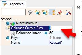


Select "Keypad1" and in the properties window set "Columns Output Pins" to 1Double click on the "Keypad1" and in the "Keys" window drag 4X "Digital Key" to the left sideClose the windowClose the window
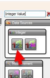
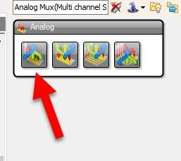
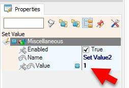
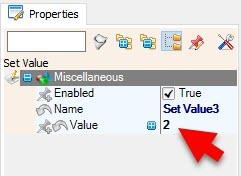
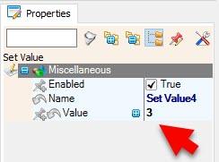
Double click on the "IntegerValue1" and in the "Keys" window drag 4X "Set Value" to the left side, for each set value in the properties window:Set Value1 > Value=0Set Value2 > Value=1Set Value3 > Value=2Set Value4 > Value=3Select "AnalogMux1" andin the properties window set "Input Pins" to 1
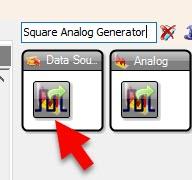
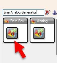
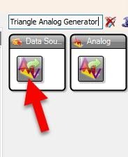
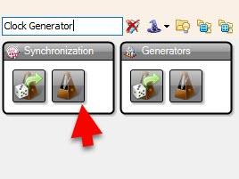
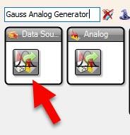
Select "ClockGenerator1" and in the properties set "Frequency" to 5Select "SineAnalogGenerator1" and in the properties set "Frequency" to 7Select "TriangleAnalogGenerator1" and in the properties set "Frequency" to 3
Step 5: In Visuino Connect Components
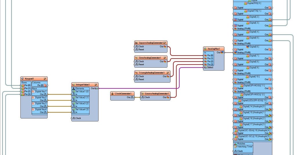
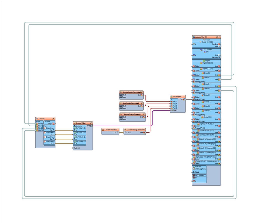
Connect Arduino Digital Pin[2] to "Keypad1" > Rows Pin [0]Connect Arduino Digital Pin[3] to "Keypad1" > Rows Pin [1]Connect Arduino Digital Pin[4] to "Keypad1" > Rows Pin [2]Connect Arduino Digital Pin[5] to "Keypad1" > Rows Pin [3]
Connect "Keypad1" > Keys > Digital Key1 Pin [Out] to "IntegerValue1" > "Set Value0" Pin[In]Connect "Keypad1" > Keys > Digital Key2 Pin [Out] to "IntegerValue1" > "Set Value1" Pin[In]Connect "Keypad1" > Keys > Digital Key3 Pin [Out] to "IntegerValue1" > "Set Value2" Pin[In]Connect "Keypad1" > Keys > Digital Key4 Pin [Out] to "IntegerValue1" > "Set Value3" Pin[In]Connect "IntegerValue1" Pin [Out] to "AnalogMux1" pin [Select]
Connect "SquareAnalogGenerator1" Pin [Out] to "AnalogMux1" Pin [0]Connect "SineAnalogGenerator1" Pin [Out] to "AnalogMux1" Pin [1]Connect "TriangleAnalogGenerator1" Pin [Out] to "AnalogMux1" Pin [2]Connect "ClockGenerator1" Pin [Out] to "GaussAnalogGenerator1" Pin[In]Connect "GaussAnalogGenerator1" Pin [Out] to "AnalogMux1" Pin [2]
Connect "AnalogMux1" Pin [Out] Arduino Digital pin [ 6 ].Analog PWM
Step 6: Generate, Compile, and Upload the Arduino Code
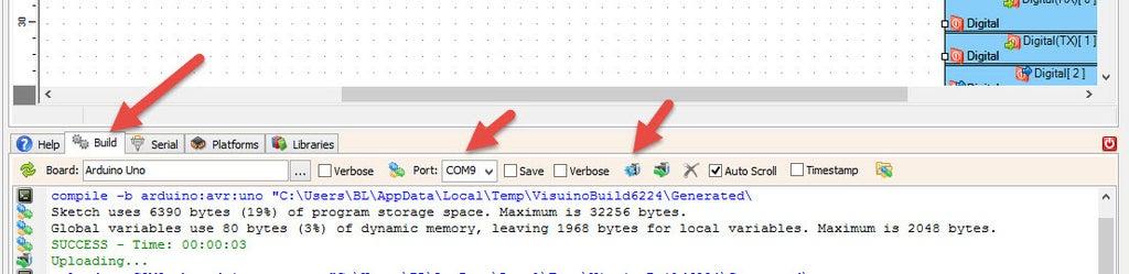
In Visuino, at the bottom click on the "Build" Tab, make sure the correct port is selected, then click on the "Compile/Build and Upload" button.
Step 7: Play
Congratulations! You have completed your project with Visuino. Also attached is the Visuino project, that I created for this Instructable, you can download it and open it in Visuino: https://www.visuino.com
Download Visuino file: Buzzer-keypad-alarm.visuino


