
In this Visuino project, you’ll learn how to easily measure and display water levels using a water level sensor and an I2C LCD — all without writing a single line of code!
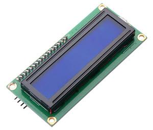
📟 The LCD shows the real-time water level value from 0.0 to 1.0 (so you can see any level in between, like 0.3 or 0.7).
💡 On the second row, it also displays a status label — Low, Medium, or High — based on the thresholds you set in Visuino.
Perfect for learning how to:
✅ Read water level using analog or digital sensors
✅ Display live readings and status on an LCD
✅ Build automatic monitoring or control systems
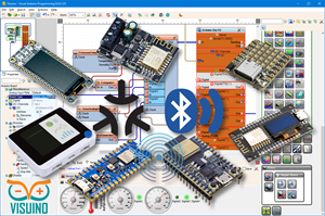
✅ Use Visuino visual programming to design Arduino projects fast and easily
📥 Download the Visuino project file at the bottom
🎥 Watch the full video to see it in action!
Step 1: What You Will Need

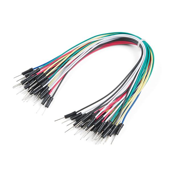
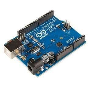
Arduino UNO (Or any other Arduino)Water Level sensorLCD I2C DisplayJumper wiresVisuino program: Download Visuino
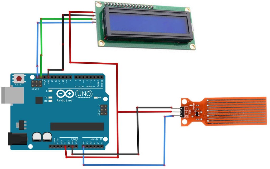
Step 2: The Circuit
Step 3: Start Visuino, and Select the Arduino UNO Board Type

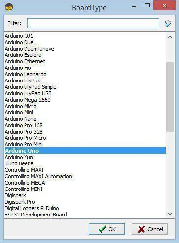
Start Visuino as shown in the first picture Click on the "Tools" button on the Arduino component (Picture 1) in Visuino When the dialog appears, select "Arduino UNO" as shown on Picture 2
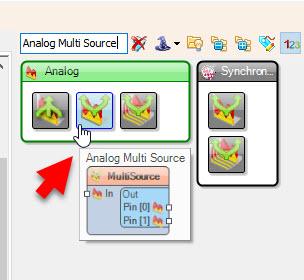
Step 4: In Visuino Add Components


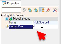
Step 5: In Visuino Set Components
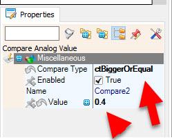
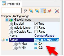
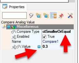

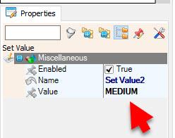
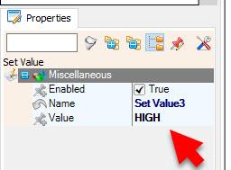

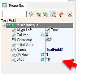
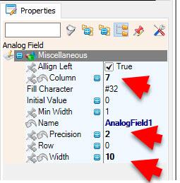
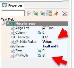
Double click on the "TextValue1" and in the Elements window drag "Set Value" to the left side and in the properties window set "Value" to LOWDrag another "Set Value" to the left side and in the properties window set "Value" to MEDIUMDrag another "Set Value" to the left side and in the properties window set "Value" to HIGHDouble click on the "LiquidCrystalDisplay1" and in the Elements window drag "Text Field" to the left side and in the properties window set "Initial Value" to VALUE: and "Width" to 6Drag another "Text Field" to the left side and in the properties window set "Row" to 1in the Elements window drag "Analog Field" to the left side and in the properties window set "Column" to 7 and "Width" to 10 and "Precision" to 2
Step 6: In Visuino Connect Components
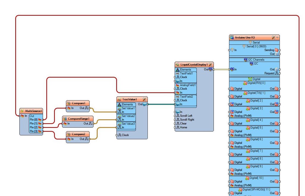
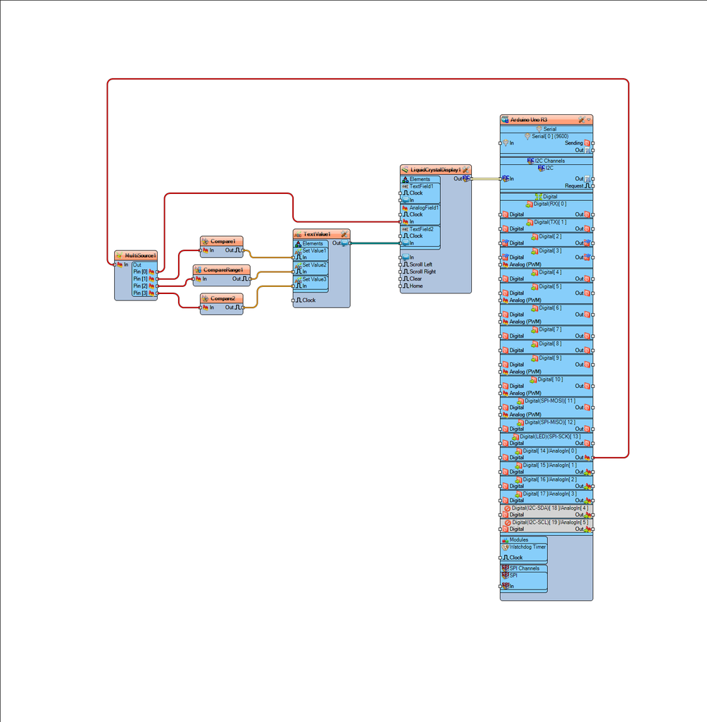
Connect Arduino Analog pin [ 0 ] to "MultiSource1" pin [In]Connect "LiquidCrystalDisplay1" pin [I2C Out] to "Arduino.I2CChannels.I2C" pin [In]Connect "MultiSource1" Pin [0] to "LiquidCrystalDisplay1" > "AnalogField1" pin [In]Connect "MultiSource1" Pin [1] to "Compare1" pin [In]Connect "MultiSource1" Pin [2] to "CompareRange1" pin [In]Connect "MultiSource1" Pin [3] to "Compare2" pin [In]Connect "Compare1" pin [Out] to "TextValue1" > "Set Value1" Pin [In]Connect "CompareRange1" pin [Out] to "TextValue1" > "Set Value2" Pin [In]Connect "Compare2" pin [Out] to "TextValue1" > "Set Value3" Pin [In]Connect "TextValue1" Pin[Out] to "LiquidCrystalDisplay1" > "TextField2" pin [In]
Step 7: Generate, Compile, and Upload the Arduino Code
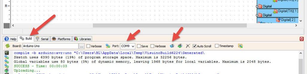
In Visuino, at the bottom click on the "Build" Tab, make sure the correct port is selected, then click on the "Compile/Build and Upload" button.
Step 8: Play
Congratulations! You have completed your project with Visuino. Also attached is the Visuino project, that I created for this tutorial, you can download it here and open it in Visuino: https://www.visuino.eu


