

This is the IoT deep dive bootcamp's pet plant, an example of midterm two assignment.

Things used in this project
Software apps and online services
Microsoft Visual Studio Code Extension for Arduino
Hand tools and fabrication machines
Soldering iron (generic)
Solder Flux, Soldering
Story
Designing an Automated Houseplant Life-Support System

Phase 1: Conceptualization & Hardware Selection
The goal of this project was to transition from manual, reactive plant care to an automated, data-driven ecosystem. The system needed to monitor ambient environmental conditions, track soil moisture in real-time, safely trigger an automated irrigation cycle, and provide both localized and remote user interfaces.
To achieve this, I selected a robust component stack balancing precision sensing with isolated power control:
• Microcontroller: Managed the central logic loop, I2C communication, and Wi-Fi telemetry.
• Environmental Sensing: A BME280 sensor captured ambient room temperature, barometric pressure, and relative humidity via I2C.
• Soil Monitoring: A capacitive SEEED Studio Soil Moisture Sensor provided an analog voltage representative of volumetric water content, mitigating the corrosion issues typical of resistive probes.
• Local UI: A 128x64 OLED Display served as the physical dashboard, rendering real-time local telemetry for quick spot-checks.
• Isolated Drive Circuit (The Pump): Operating a mechanical inductive load like a water pump directly from a microcontroller GPIO is a recipe for fried silicon. I engineered an isolated driver using a 2N3906 PNP Transistor configured as an emitter follower to source current safely to a Relay. The relay contacts isolated the noisy, higher-current 5V/12V pump circuit from the sensitive logic rails.
Phase 2: Hardware Prototyping & Electrical Engineering

With the components selected, I moved to the breadboard to construct the electrical backbone.
[Microcontroller GPIO] ---> Base [2N3906 PNP]
                                      |---> Emitter [Relay Coil + Flyback Diode] ---> GND
• The Driver Circuit: I wired the 2N3906 transistor, ensuring the inclusion of a flyback diode across the relay coil to suppress inductive voltage spikes during switching.
• The Sensor Bus: The BME280 and OLED were multiplexed onto the hardware I2C bus, utilizing proper pull-up resistors to maintain signal integrity. The SEEED sensor was routed to a dedicated Analog-to-Digital Converter (ADC) pin.
• Physical Enclosure & Mechanical Integration: Moving beyond a messy breadboard, I sourced a physical structural housing to neatly organize the plant, the reservoir, the submersible pump, and the electronics. This kept the high-moisture environment completely isolated from the exposed circuitry.
Phase 3: Firmware Architecture & Safe Automation Logic

The software framework was built on an asynchronous, non-blocking timing loop using millis() rather than blocking delay() functions, ensuring the system remained responsive to incoming remote commands.
• The Safe-Watering Algorithm: Continuous irrigation risks drowning the plant roots or flooding the enclosure. I implemented a strict, short-pulse logic constraint: when soil moisture dropped below the calibrated threshold, the pump was initialized for exactly 0.5 seconds (500ms) before cutting power and entering a cooldown period. This allowed the water time to diffuse through the soil before the next sensor reading.
• Edge Display: Code was written to continuously refresh the OLED screen, cycling through local diagnostics (Temperature, Humidity, and Moisture %).
Phase 4: IoT Telemetry & Adafruit.io Dashboard

Automation is only as good as its visibility. I configured a secure Wi-Fi client on the microcontroller to publish data packages to Adafruit.io.
• Data Streams: I created distinct feeds for Soil Moisture, Temperature, Humidity, and Pressure.
• UI Design: I built a clean, user-friendly remote dashboard featuring real-time gauges for environmental metrics and linear charts tracking historical moisture degradation trends.
• Bi-Directional Manual Override: I integrated a digital push-button widget onto the Adafruit.io dashboard. By subscribing the microcontroller to this specific command feed, I enabled a manual override. Pressing the cloud button sends an instant MQTT packet to the controller, safely triggering the exact same 0.5-second watering burst from anywhere in the world.
Phase 5: Cloud Integration & Webhooks via Zapier
To close the loop on systemic awareness, I extended the project into the broader internet ecosystem using Zapier.
• I configured an Adafruit.io reactive trigger (reactive action) to monitor the soil moisture feed.
• When the moisture levels breach a critical drought threshold, the system dispatches an outbound webhook payload to Zapier.
• Zapier parses the incoming JSON data and instantly fires an automated SMS alert and email notification to my phone, alerting me that the automation system is intervening.
Phase 6: Testing, Documentation, and Delivery

The final phase shifted from engineering to public-facing documentation and presentation:
• The Codebase: I structured a clean, modular production folder, scrubbed my personal Wi-Fi and Adafruit.io API credentials into a secured secrets.h file, and pushed the complete directory to a new public GitHub Repository for open-source review.
• The Feed: I drafted a comprehensive step-by-step project build guide on Hackster.io, detailing the schematic layouts, component bills of materials, and calibration challenges.
• The Demo: I recorded a concise video demonstration showcasing the live system: tracking ambient data, triggering a tight 0.5-second automated pulse, demonstrating the dashboard's manual override button, and showing the resulting cloud telemetry charts.
• The Presentation: The project culminated in a live classroom presentation using the Hackster layout, active Adafruit.io dashboards, and the video demo to demonstrate full system integration to peers and instructors.
Schematics
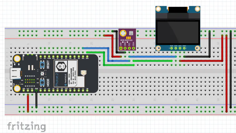
this is placer fritzing
fritzing is of the photon2 a bme280 sensor and a OLED display
/*
 * Project HarryPotterBuzzer
 * Author: Jamie Dowden-Duarte
 * Date: 7.7.2024
 * For comprehensive documentation and examples, please visit:
 * https://docs.particle.io/firmware/best-practices/firmware-template/
 */

// Include Particle Device OS APIs
#include "Particle.h"
#include "Adafruit_SSD1306.h"
#include "Adafruit_GFX.h"
#include "neopixel.h"
#include "IoTClassroom_CNM.h"
// Let Device OS manage the connection to the Particle Cloud
SYSTEM_MODE(SEMI_AUTOMATIC);

const int BUZZ = D14;
const int OLED_RESET = -1;
const int PIXELCOUNT = 46;
#define WIDTH  78
#define HEIGHT 64
const unsigned char HP[] PROGMEM = {
  0x00,0x00,0x00,0x00,0x00,0x00,0x00,0x00,0x00,0x00,
  0x00,0x00,0x00,0x00,0x00,0x00,0x00,0x00,0x00,0x00,
  0x00,0x00,0x00,0x00,0x00,0x00,0x00,0x00,0x00,0x00,
  0x00,0x00,0x00,0x00,0x00,0xFC,0x00,0x00,0x00,0x00,
  0x00,0x00,0x00,0x00,0x0F,0xFF,0xE0,0x00,0x00,0x00,
  0x00,0x00,0x00,0x00,0x7F,0xFF,0xFC,0x00,0x00,0x00,
  0x00,0x00,0x07,0xFD,0xFF,0xFF,0xFF,0x00,0x00,0x00,
  0x00,0x00,0x3F,0xFF,0xFF,0xFF,0xFF,0x80,0x00,0x00,
  0x00,0x00,0xFF,0xFF,0xFF,0xFF,0xFF,0xE0,0x00,0x00,
  0x00,0x03,0xFF,0xFF,0xFF,0xFF,0xFF,0xF0,0x00,0x00,
  0x00,0x07,0xFF,0xFF,0xFF,0xFF,0xFF,0xF8,0x00,0x00,
  0x00,0x0F,0xFF,0xFF,0xFF,0xFF,0xFF,0xFC,0x00,0x00,
  0x00,0x1F,0xFF,0xFF,0xFF,0xFF,0xFF,0xFE,0x00,0x00,
  0x00,0x18,0x7F,0xFF,0xFF,0xFF,0xFF,0xFF,0x00,0x00,
  0x00,0x00,0xFF,0xFF,0xFF,0xFF,0xFF,0xFF,0x80,0x00,
  0x00,0x03,0xFF,0xFF,0xFF,0xFF,0xFF,0xFF,0xC0,0x00,
  0x00,0x07,0xFF,0xFF,0xFF,0xFF,0xFF,0xFF,0xC0,0x00,
  0x00,0x0F,0xFF,0xFF,0xFF,0xFF,0xFF,0xFF,0xE0,0x00,
  0x00,0x1F,0xFF,0xFF,0xFF,0xFF,0xFF,0xFF,0xE0,0x00,
  0x00,0x1F,0xFF,0xFF,0xFF,0xFF,0xFF,0xFF,0xF0,0x00,
  0x00,0x3F,0xFF,0xFF,0xFF,0xFF,0xFF,0xFF,0xF0,0x00,
  0x00,0x3F,0xFF,0xFF,0xFF,0xFF,0xFF,0xFF,0xF8,0x00,
  0x00,0x7F,0xFF,0xFF,0xFF,0xFF,0xFF,0xFF,0xF8,0x00,
  0x00,0x7F,0xFF,0xFF,0xFF,0xFF,0xFF,0xFF,0xFC,0x00,
  0x00,0x7F,0xFF,0xFF,0x83,0xFF,0xFF,0xFF,0xFC,0x00,
  0x00,0x7F,0xFF,0xFE,0x01,0xFF,0xFF,0xBF,0xFC,0x00,
  0x00,0x7F,0xFF,0xF8,0x00,0x7F,0xFF,0x9F,0xFC,0x00,
  0x00,0x7F,0xFF,0xF0,0x00,0x3F,0xFF,0x8F,0xFC,0x00,
  0x00,0x7F,0xFF,0xC1,0x80,0x3F,0xFF,0x0F,0xFC,0x00,
  0x00,0x7F,0xFF,0xC0,0xC0,0x1F,0xFF,0x07,0xFC,0x00,
  0x00,0x7F,0xFF,0x80,0x60,0x0F,0xFE,0x03,0xFC,0x00,
  0x00,0x7F,0x7F,0x00,0x30,0x0F,0xFE,0x03,0xFC,0x00,
  0x00,0x7F,0x3F,0x00,0x10,0x07,0xFC,0x03,0xFC,0x00,
  0x00,0x7F,0x3F,0x00,0x70,0x07,0xF8,0x01,0xFC,0x00,
  0x00,0x3E,0x1E,0x01,0xC0,0x03,0xF0,0x01,0xFC,0x00,
  0x00,0x3E,0x0E,0x00,0xC0,0x03,0xE0,0x01,0xFC,0x00,
  0x00,0x3E,0x02,0x00,0x60,0x01,0xC0,0x00,0xFC,0x00,
  0x00,0x3E,0x00,0x00,0x20,0x01,0x80,0x00,0xFC,0x00,
  0x00,0x1E,0x00,0x00,0x10,0x00,0x00,0x00,0xF8,0x00,
  0x00,0x1E,0x00,0xFE,0x00,0x00,0x3F,0x00,0xF8,0x00,
  0x00,0x1E,0x03,0xFF,0x80,0x01,0xFF,0xE0,0x78,0x00,
  0x00,0x0E,0x0F,0x01,0xC0,0x03,0xC0,0xF0,0x70,0x00,
  0x00,0x0C,0x1C,0x00,0x60,0x07,0x00,0x38,0x70,0x00,
  0x00,0x0E,0x38,0x00,0x30,0x0C,0x00,0x1C,0x70,0x00,
  0x00,0x06,0x30,0x00,0x18,0x1C,0x00,0x0E,0x60,0x00,
  0x00,0x06,0x60,0x00,0x18,0x18,0x00,0x06,0x20,0x00,
  0x00,0x02,0x60,0x00,0x0D,0xB0,0x00,0x06,0x00,0x00,
  0x00,0x00,0x60,0x00,0x0F,0xF0,0x00,0x03,0x00,0x00,
  0x00,0x00,0xC0,0x00,0x0E,0x70,0x00,0x03,0x00,0x00,
  0x00,0x00,0xC0,0x00,0x04,0x30,0x00,0x03,0x00,0x00,
  0x00,0x00,0xC0,0x00,0x04,0x30,0x00,0x03,0x00,0x00,
  0x00,0x00,0xC0,0x00,0x0C,0x30,0x00,0x03,0x00,0x00,
  0x00,0x00,0x60,0x00,0x0C,0x30,0x00,0x03,0x00,0x00,
  0x00,0x00,0x60,0x00,0x0C,0x30,0x00,0x06,0x00,0x00,
  0x00,0x00,0x60,0x00,0x18,0x18,0x00,0x06,0x00,0x00,
  0x00,0x00,0x30,0x00,0x18,0x1C,0x00,0x0C,0x00,0x00,
  0x00,0x00,0x18,0x00,0x30,0x0E,0x00,0x1C,0x00,0x00,
  0x00,0x00,0x1C,0x00,0x60,0x07,0x00,0x38,0x00,0x00,
  0x00,0x00,0x0F,0x01,0xC0,0x03,0xC0,0xF0,0x00,0x00,
  0x00,0x00,0x03,0xFF,0x80,0x01,0xFF,0xC0,0x00,0x00,
  0x00,0x00,0x00,0xFC,0x00,0x00,0x3F,0x00,0x00,0x00,
  0x00,0x00,0x00,0x00,0x00,0x00,0x00,0x00,0x00,0x00,
  0x00,0x00,0x00,0x00,0x00,0x00,0x00,0x00,0x00,0x00,
  0x00,0x00,0x00,0x00,0x00,0x00,0x00,0x00,0x00,0x00
};

// void singHarryPotter();
void pixelFill(int start, int end, int color);

Adafruit_SSD1306 display(OLED_RESET);
Adafruit_NeoPixel pixel(PIXELCOUNT, SPI1, WS2812B);

void setup() {
  display.begin(SSD1306_SWITCHCAPVCC, 0X3C);
  display.clearDisplay();
  display.drawBitmap(0, 0, HP, WIDTH, HEIGHT, WHITE);
  display.display();
  pixel.begin();
  pixel.setBrightness(25);
  pixelFill(0,11,red);
  pixelFill(12,23,green);
  pixelFill(24,35,blue);
  pixelFill(35,46,yellow);
}

void loop() {
//  singHarryPotter();
  tone(BUZZ,9877,476);
  tone(BUZZ,1318,1428);
  tone(BUZZ,1567,476);
  tone(BUZZ,1479,952);
  tone(BUZZ,1318,2857);
  tone(BUZZ,1975,1428);
  tone(BUZZ,1760,1428);
  tone(BUZZ,1479,3333);
  tone(BUZZ,1318,1428);
  tone(BUZZ,1567,476);
  tone(BUZZ,1479,952);
  tone(BUZZ,1244 ,1428);
  tone(BUZZ,1396,952);
  tone(BUZZ,9877,2857);

}


void pixelFill(int start, int end, int color)
{
    int i;
    for (i = start; i <= end; i++)
    {
        pixel.setPixelColor(i, color);
        pixel.show();
    }

}
// void singHarryPotter(){
//   tone(BUZZ,98777,476);
//   tone(BUZZ,13185.1,1428);
//   tone(BUZZ,15679.8,476);
//   tone(BUZZ,14799.18,952);
//   tone(BUZZ,13185.1,2857);
//   tone(BUZZ,19755.3,1428);
//   tone(BUZZ,17600,1428);
//   tone(BUZZ,14799.8,3333);
//   tone(BUZZ,13185.1,1428);
//   tone(BUZZ,15679.8,476);
//   tone(BUZZ,14799.8,952);
//   tone(BUZZ,12445.1 ,1428);
//   tone(BUZZ,13969.1,952);
//   tone(BUZZ,9877.7,2857);
// }
This project is adapted from the original project by Jamie Dowden-Duarte on Hackster.io.
Original project: Classroom Automated House Plant Project