In this instructable we will be building a temperature probe that utalizes MQTT and Home Assistant to relay the temperature information to a webpage where you can monitor the germination temp anywhere of your fermenter.
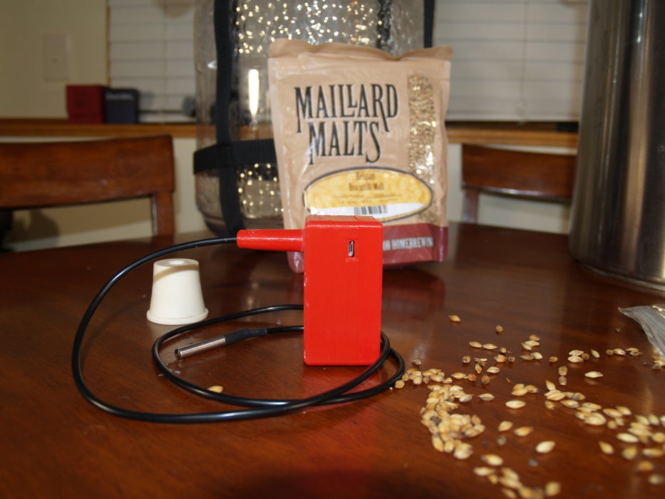
I the complete list of things to have for this is as follows:
- Arduino Code and 3D Model files
- Waterproof DS18B20 Sensor Kit: $8
- Have to install by hand onewire library
- Need to install the arduinoJson library Add to the boards manager URLs.
- Need to add the firebeetle library
Items to purchase to aid in the construction:
- Great Planes Double-Sided Servo Tape 1x3'
Step 1: Soldering the Firebeetle
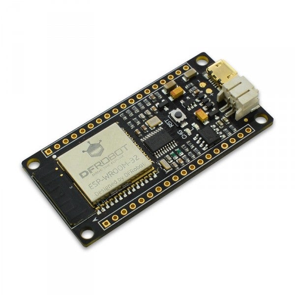
Now you will need to solder an included header to only one side of the firebeetle. It will be the side with the VCC on it.
Step 2: Change Housing
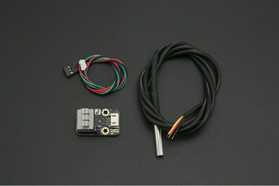
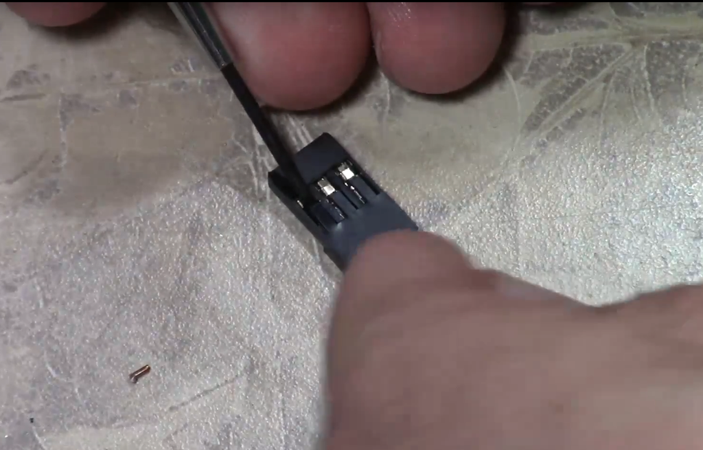
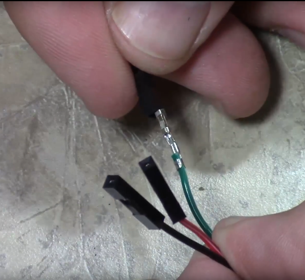
First you will need to remove the housing from the thermal probe connector and replace it with single housing for each pin.
You can pick up a housing pin from the following:
Step 3: Solder Wires to Micro USB
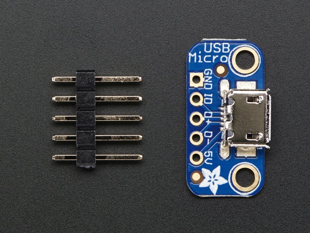
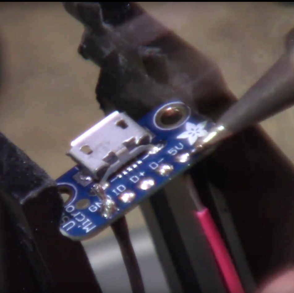
Now you will need to solder power and ground wires to the mirco usb breakout board sot that you can power the unit from a micro usb connection.
Step 4: Solder Breakout to Firebeetle
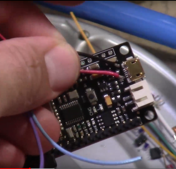
Now you need to look at the micro USB port on the Firebeetle. There are two pads labeled "+" and "-". They will be where you will connect your power and ground from the USB breakout board.
Step 5: 3D Print the Case
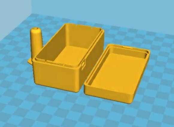
Now you will need to 3D Print the case. The model files can be located at the following:
https://www.thingiverse.com/thing:2502515
Step 6: Glue the Insert
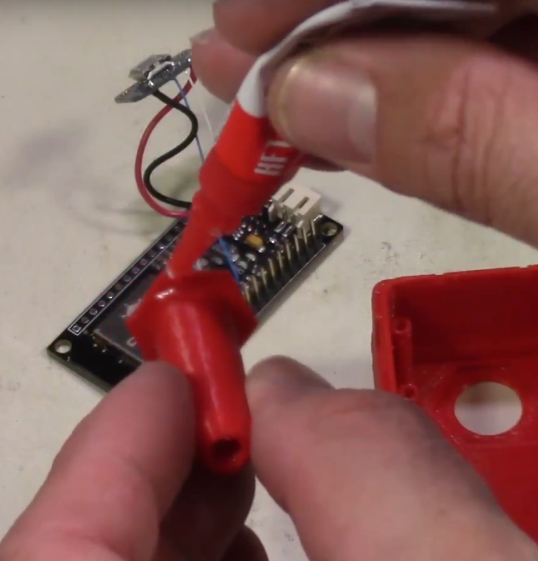
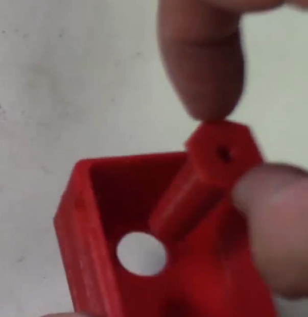
Now you will need to apply glue to the hex headed insert and then insert it into the main body of the housing.
Step 7: Place Double Back Tape
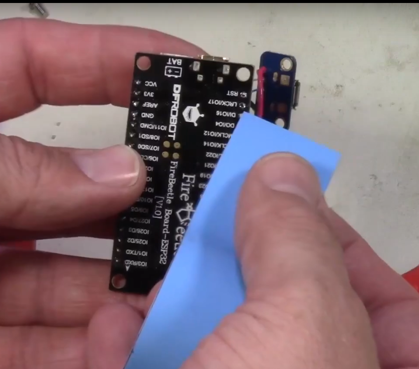
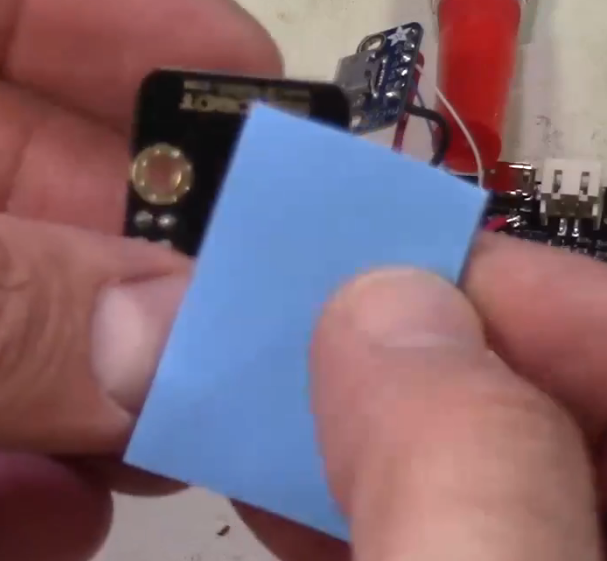
Put the double back tape on the back of the firebeetle and the back of the temperature breakout board as well to install.
Step 8: Make Conections
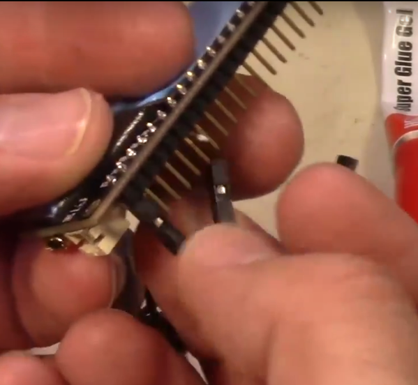
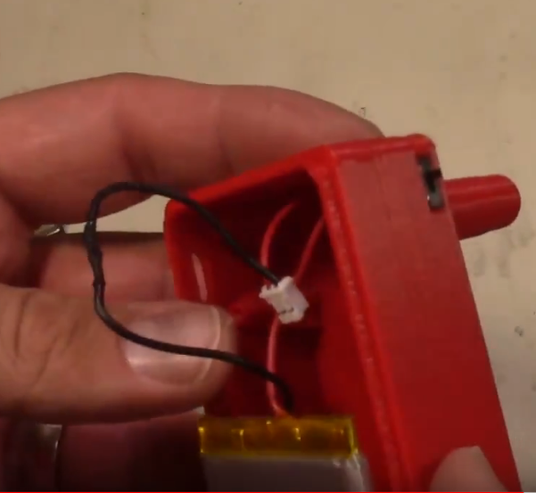
You will connect the red pin to the VCC and the Black pin to the Ground. You will connect the sens pin to the GPIO D6 on the firebeetle.
Also you will need to connect the switch in series with the power line coming from the LiPo Battery. This way when you switch the switch it controls the power to the unit.
Step 9: Coding - Firebeetle
Now you will need to edit the code for your application.
The section will be as follows:
const PROGMEM char* MQTT_CLIENT_ID = "";
const PROGMEM char* MQTT_SERVER_IP = "";
const PROGMEM uint16_t MQTT_SERVER_PORT = 1883;
const PROGMEM char* MQTT_USER = "";
const PROGMEM char* MQTT_PASSWORD = "";
const PROGMEM char* MQTT_SENSOR_TOPIC = "";
Step 10: Installing Libraries for Firebeetle
In your arduino software you will need to go to file -> preferences. Then in the "Additional Boards Manager URLs:" section you will add the following two links with a comma in between.
https://git.oschina.net/dfrobot/FireBeetle-ESP32/r…
Next go to Tools -> Board -> Boards Manager... and search for firebeetle. Choose the "FireBeetle-ESP32 Mainboard by DFrobot DFRDuino" and install it.
Finally you need to go to Sketch -> Include Library -> Manage Libraries... and you will search for the following:
ArduinoJson by Benoit Blanchon (install this)
onewire
pubsubclient
Once finished with this you will install the code you have by choosing the firebeetle board, connecting a USB cable to it, choosing the com port it is on in the arduino menu, and uploading the sketch.
Step 11: Home Assistant .yaml File Setup
Now you will need to go to your configuration.yaml file for your home assistant instance. Once you are into editing this file you will need to add the following configuraiton:
#somewhere at the top add
mqtt:
#then you need to add the following sensor
sensor 1:
platform: mqtt
state_topic: ''
name: ''
unit_of_measurement: '°F'
value_template: '{{ value_json.temperature }}'
Step 12: Install the Hardware
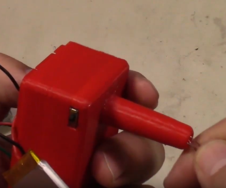
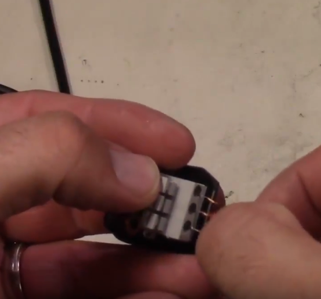
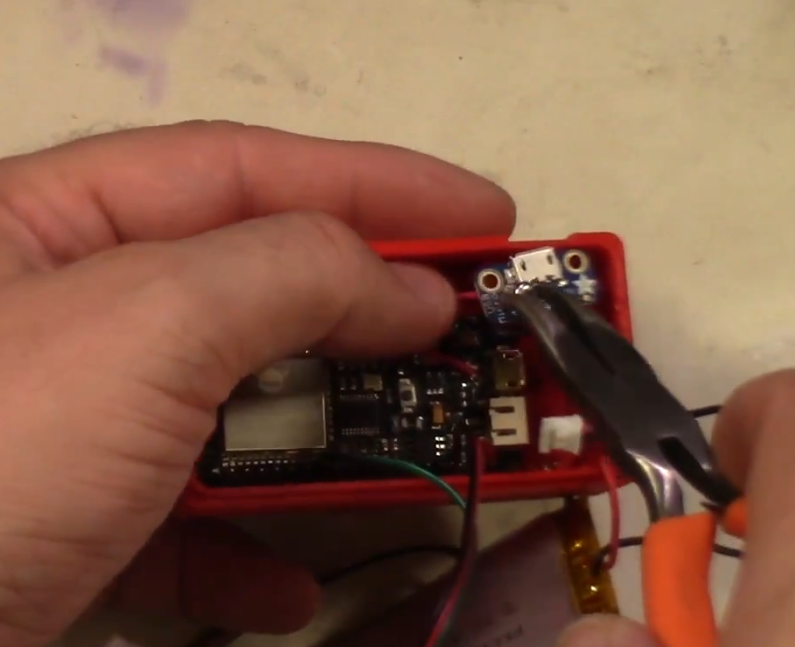
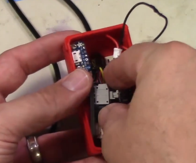
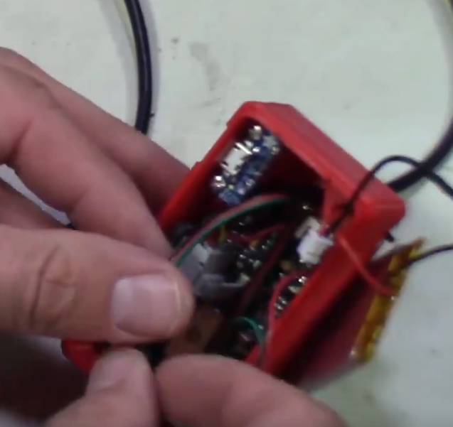
You will install the firebeetle in the bottom of the case by removing the double backed tape and sticking it down to the inside of the case.
Install the USB breakout on the two stand-offs that are on the side. Use two small screws to secure it.
You will then feed the temp probe through the insert and connect the Red wire to the Power, Black to the Ground, and Yellow to the signal pin of the temp probe breakout board.
Finally install the breakout board into the side of the case by peeling off the backing on the tape and securing it to the side where it does not interfere with the other components.
Lastly you will need to plug in the battery and tuck all the wires inside the case.
Step 13: Secure Battery to Lid
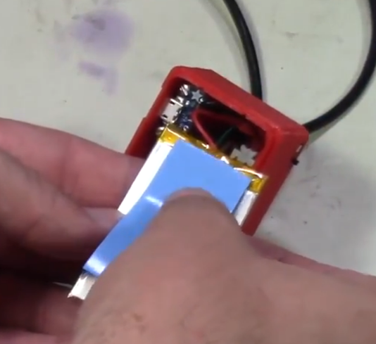
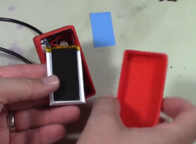
Now you will need to simply attach the battery to the lid by the same method of applying some double stick tape to the battery pack and then sticking it to the lid of the unit.
Once the battery is in place you can now snap the lid over the case and turn it on!!
Step 14: More Details
If you would like more details please check out the video on how to build this and at the end there is a link to the in-depth video with full build procedure laid out for you.
----------------------------------------------------------------------
Try Amazon Prime 30-Days https://www.amazon.com/tryprimefree?r...
Support the channel tip with bitcoins Address: 1MvcZHRb Dm9czS8s776iutBBPJ39K4PEHh
Follow me on Instructables https://www.instructables.com/member/m...
Follow me on Facebook https://www.facebook.com/misperryee/
Follow me on Twitter https://twitter.com/misperryee
The article was first published in Instructables
cr: https://www.instructables.com/The-Brew-Probe-WiFi-Temperature-Monitor/
author: misperry


