
Upgrading an old thermostat to a smart system featuring an HTTP server on a Raspberry Pi and a mesh network of ESP32 thermometers.

I have a pretty old heating system with an old Honeywell thermostat that is mechanical rather than electric. It works well but can only track the temperature in the main room. It’s pretty hard to control the temperature in the bedroom on the second floor when the thermostat is located on the first floor in a cold room. It will never know when to stop the heating system.
How does the Honeywell thermostat work?
The old Honeywell thermostat is genius and dumb at the same time. It has a glass tube with a silver liquid inside. Mercury is typically found in older mechanical thermostats like the Honeywell Round T87 and rectangular T8090. It has a flat spiral spring, and the tube is on top. The spring bends with cold, and the mercury in the tube falls and closes the electrical circle. When it heats, it unbends, and mercury goes to the other side of the tube and opens the circuit. It's straightforward, reliable, and fault-proof because it’s physics. However, this system is outdated, and modern thermostats use electronics.
Of course, there are new mechanical thermostats that don’t have mercury, but they still have the same pros and cons:
Pros:
· Reliable
· Fault proof
Cons:
· Controls heating only in one room
· Constant temperature until changed physically
It can’t be controlled remotely.
· No schedules, no options
· Requires wires
What are the options to upgrade?
A thermostat is a relay device that opens and closes an electric circle based on the temperature around it. If we think about it, we can find that any relay device could do the same if it has a temperature value. There are tons of ready-to-go solutions, like Ecobee or Google Nest. But anyway, it should be integrated into your heating system, so we need to figure out what it is and how to add something smart.
System design
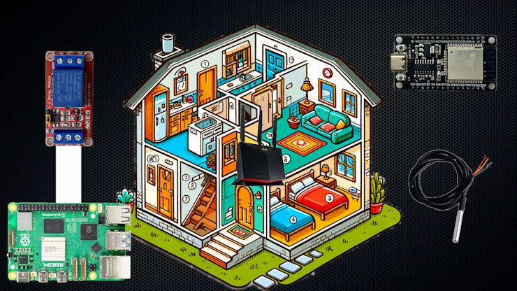
To upgrade this system, I will need a few thermosensors in various rooms and a small server equipped with a relay. The server board will receive all the data from the thermometers and either close or open the electrical circuit. I've decided to build the new smart house system with the following elements:
Raspberry Pi - the main board or a server. It will be a decision center.A Relay device that will be connected to the Raspberry Pi with wires. The relay is an electrically operated switch. It will turn the heating system on and off.A home Wi-Fi router. By this, I mean any Wi-Fi router that provides coverage in each room.An ESP32 device is a small chipboard with Wi-Fi and can obtain data from external sensors.A DS18B20 thermal sensor. This is essentially a thermometer that can provide the current temperature of the surroundings.
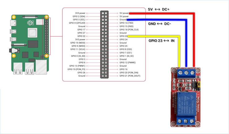
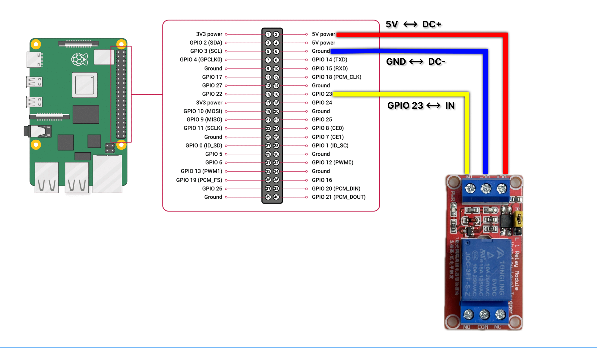
The Raspberry Pi connection is simple. The 5-volt pin is connected to the relay's DC+, the ground pin to DC-, and GPIO 23 to the relay's input. Overall, assembly took 5 minutes. I didn't use solder; it was just plug-and-play.
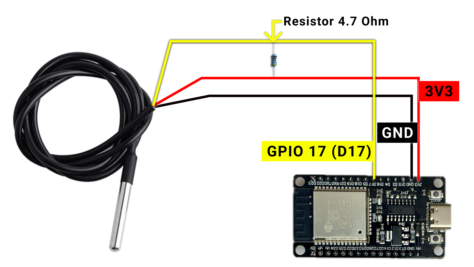
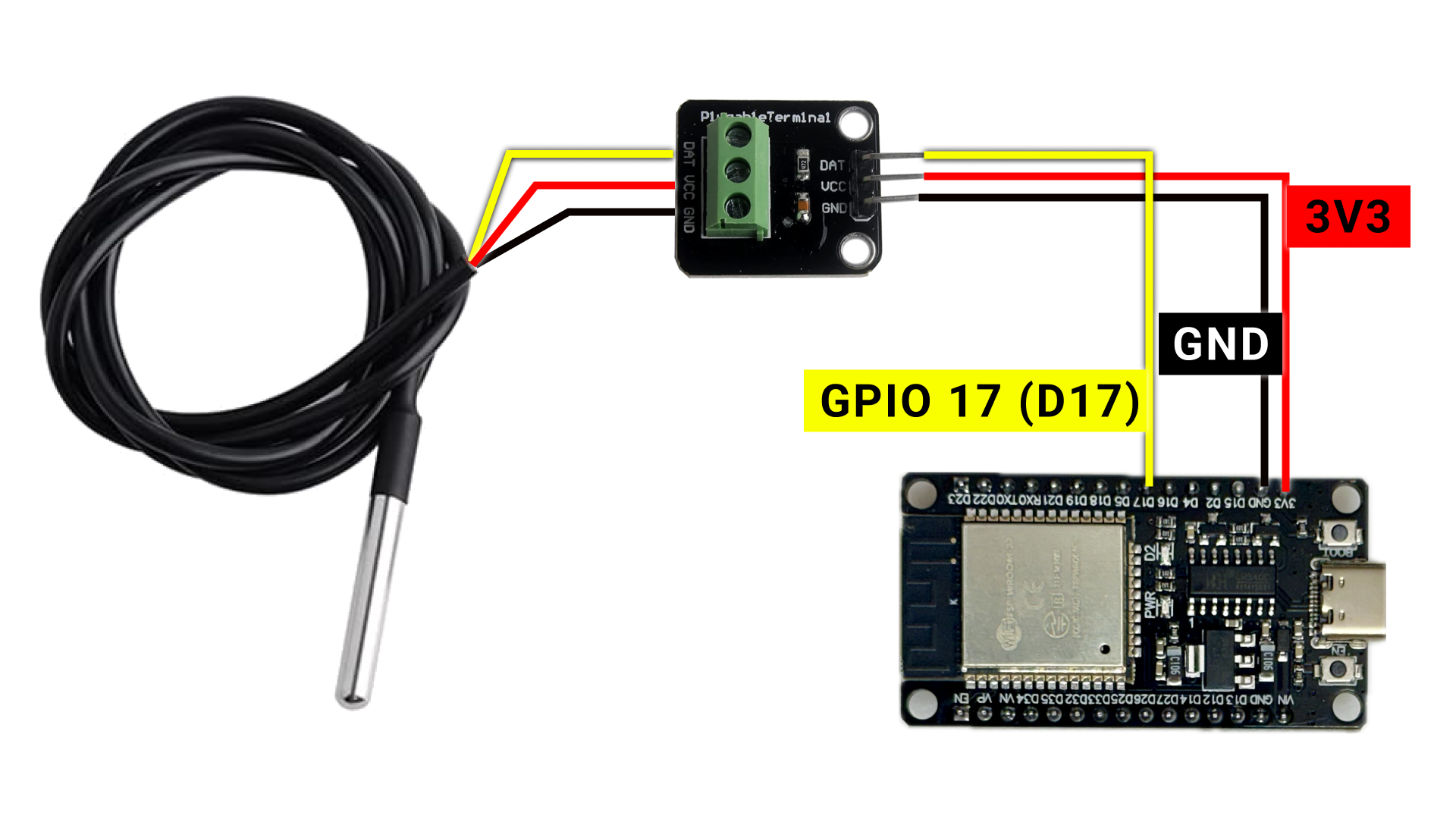
The ESP32 board and the thermometer scheme:

I have a video on the channel about different options for using a resistor or connecting directly to the board:
The remaining task is to equip the boards with the appropriate software to bring them to life. In my case, I used a Node.js HTTP server on the Raspberry Pi. It listens for network calls from the sensors, and this server decides when to activate or deactivate the relay.
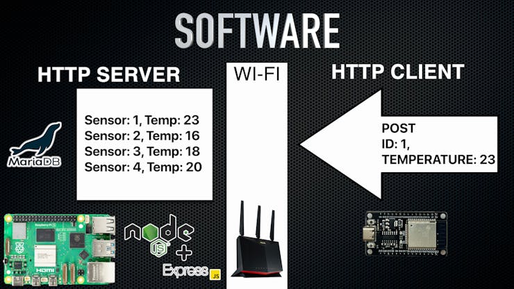
The ESP board is an HTTP client that periodically sends the current sensor's temperature data. Let's say the ESP board sends a POST request to the Raspberry Pi every minute with the temperature and sensor ID. The Raspberry Pi will store the status in a database and maintain a log of temperatures from all sensors. At any given moment, the Raspberry Pi knows if it has current data for the room that should be heated to a certain degree. If the room is underheated, the server will activate the relay. The server will deactivate the relay once the room reaches the required temperature.
Codebase
I've created a GitHub repository:
https://github.com/Nerdy-Things/openheat
We can use git to download the code:
ã€git clone https://github.com/Nerdy-Things/openheat.git】
The project has two folders:
· esp32ds18b20
· has the C project for theESP32 thermometer
· raspberry
· has the NodeJs server that should be installed on the Raspberry PI
ESP32 software
If you want to build & flash the ESP32 with the DS18B20 sensor, you need to open the esp32ds18b20 folder in the Visual Studio Code. It also requires an ESP-IDF plugin.
· main — application entry point. app_main.c -> void app_main will be triggered when you install the software on ESP32.
· nerdy_mac_address — provides a mac address of the device. We will use this Mac address to differentiate several ESP boards.
· nerdy_http_request — sends POST requests to the server.
· nerdy_wifi — connects ESP32 board to the Wi-Fi network.
· nerdy_temperature — it provides a temperature value from the sensor.
To set up ESP32 software, you should copy a file:
ã€esp32ds18b20/nerdy_wifi/nerdy_wifi_config.c.example】
to:
ã€esp32ds18b20/nerdy_wifi/nerdy_wifi_config.c】
And put your Wi-Fi credentials there:
ã€#define WIFI_SSID "SSID_NAME" // SET YOUR WI-FI ACCESS POINT NAME HERE
#define WIFI_PWD "SSID_PASSWORD" // SET YOUR WI-FI PASSWORD HERE】
That's it. It will be ready to go.
The app_main.c file from the main folder will:
· Connect to the Wi-Fi using the credentials above. - Initiate the temperature sensor. - Build the message:
ã€{"mac_address": "XXXXXX" , "temperature\": "00.00"}】
· And send it with a post request every 60 seconds
ã€POST /api/temperature/update HTTP/1.1
Host: openheat.local:8080
User-Agent: esp-idf/1.0 esp32
Content-Type: application/json
Content-Length: 77
Connection: close
{"mac_address": "0x8:0xd1:0xf9:0x35:0x8c:0x80" , "temperature": "17.687500"}】
Raspberry PI software
First, the SD card should be flashed with the operational system.
Luckily, it's a piece of cake https://www.raspberrypi.com/software/
Just use an Imager, and it will do the magic.
The most important part is to fill in the configuration.
· Hostname: openheat
· Username: nerdythings
· Password: nerdythings
· SSID: your Wi-Fi access point name
· Password: your Wi-Fi password
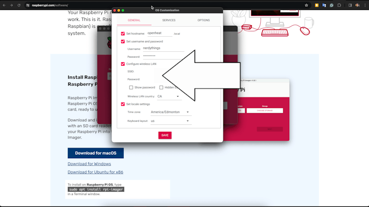
After that, press install and wait a bit.
The Imager will say when to eject the SD card. Then, we can put it into the Raspberry PI and power on it.
After a few moments, we can connect to it:
ã€ssh [email protected]】
And then download the code base to the board:
ã€git clone https://github.com/Nerdy-Things/openheat.git】
Next, we are going inside the server
ã€cd openheat/raspberry/】
Run the install script:
ã€./install.sh】
Under the hood, it will install every piece of software that we need:
· nodejs
· npm
· nginx
· mariadb-server
· pm2@latest
The script will also ask to set up the mariadb-server. So, the time has come if you see the following lines in the command line.
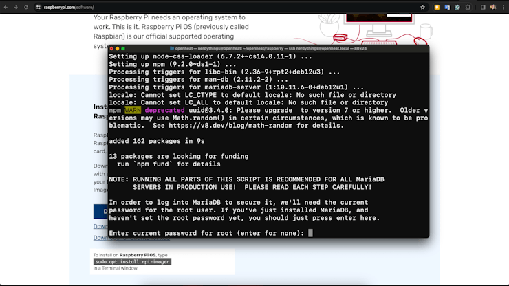
Root password - empty; press enter.
Switch to unitx_socket authentication - N
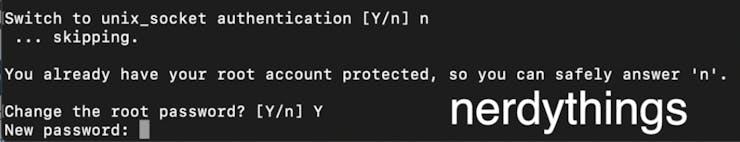
And it's essential to change the root password of the databases to the nerdythings
This password is hardcoded in the ecosystem.config.js file.
It's not secure, but the Raspberry PI will be accessible from your local network only, so I don't think that your dog will try to hack you :)
The rest of the options are up to you. It doesn't matter whether to enable them or not.
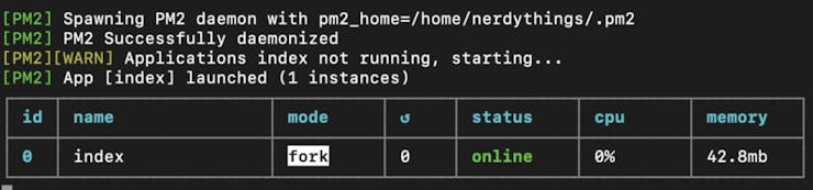
After all inputs, the installation will proceed.
The following message will mean that the server is running.
If you go to the URL: http://openheat.local:8080/, it should open something like this:

The login and password are also nerdythings (lowercase). After some time, the main page will show graphs of temperatures from all the ESP32 thermometers in your local network.
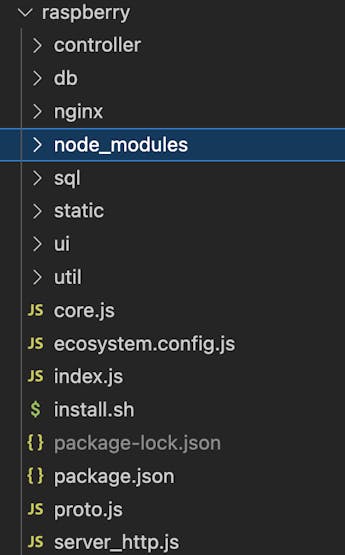
The NodeJS project is pretty simple:
The best part is to schedule the relay using the website:
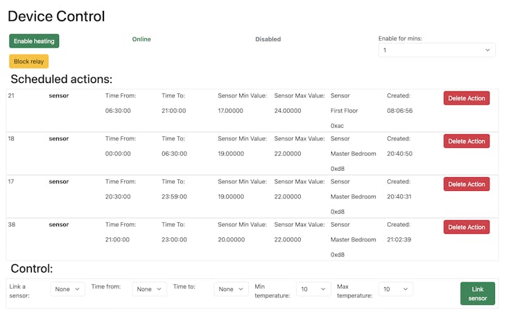
We can set the minimal temperature in the room at intervals. The first line from the table means that the relay will be enabled between 6:30 AM and 9 PM if the temperature from the sensor on the first floor is less than 17 degrees Celsius. As soon as the temperature reaches 17+, the relay will be disabled. Moreover, we can enable the relay for some duration. For example, pressing "Enable heating" will allow the relay for 1 minute (top right corner).
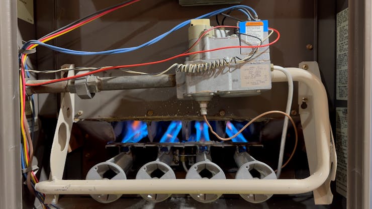
The remaining part is to connect the relay instead of the Old Thermostat. In my case, it has two wires, so it's easy to figure it out :)
By the way, youshould never fully dismount an old thermostat. It will work as a backup when the software is down, or your Wi-Fi is dead.
Additionally, do not touch your heating system unless you have the proper skills and knowledge. It could burn a house or kill someone.
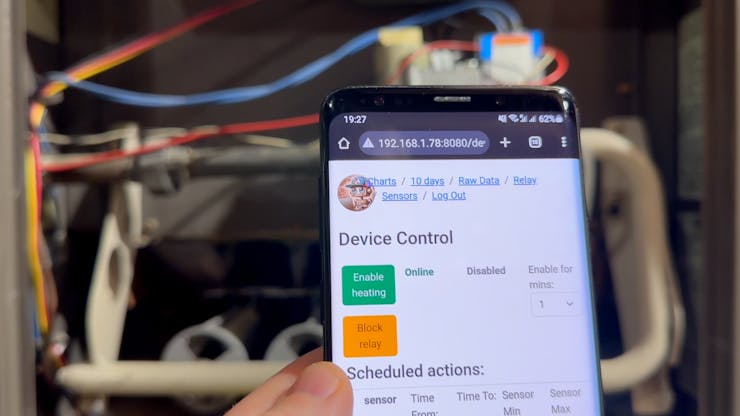
The result is incredible! I can press a button on the phone and enable the heating:
Cheers!
SchematicsESP32 Resistor
ESP32 Module
Raspberry PI Relay
Code
The article was first published in Hackster on February 16, 2024
Author: Eugene Tkachenko


