
Hello, Friends. In this blog I will show you How to Make a Gaming PC Using Lattepanda
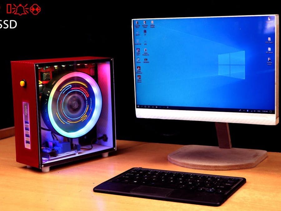
Hello, Friends. In this instructables I will show you How to Make a Gaming PC Using Lattepanda board and its Windows10 Developer board but its look like Very mini board but its powerful Operating system of this mini Computer is running windows 10 pre- installed board. I made its body from cheapest acrylic sheet, MDF wood and I have using 10 inches Display and I made this Gaming PC. I Hope you will enjoy this Instructables.
In my website DiY Projects Lab having more than 25 detailed projects so you can go through this link (click here) for a more creative and amazing projects and tutorial. That will enhance your creative mind as you grow.
First thanks to Nextpcb for sponsor This project
This project is sponsored and supported by Nextpcb
Supplies:
We need below products:(1) Lattepanda Alpha
(2)Samsung SSD
(3)USB 3.0 Hub
(4)USB 2.0 Hub
(5)Carbon Fiber Sheet Black
(6)Carbon Fiber Sheet Red
( 7)Carbon Fiber Sheet White
(8)MDF Board
(9)Thermaltek Fan
(10)Arduino
(11)Relay Module
(12)LED Strip
(13)Acrylc Sheet 3mm Transparent
(14)10 inch Display & Driver (LINK)
Step 1: Watch the Video
Step 2: LattePanda Alpha
LattePanda :- LattePanda is a single-board computer project that has achieved funding on Kickstarter and that will delight users who like these mini-PCs that have the Raspberry as the great banner.
LattePanda Alpha uses Intel Core m3 processor, which is the same as the latest MacBook. The Core m3 processor is the perfect choice for superior performance and low power consumption. With its own 8GB RAM and 64GB eMMC, M.2 interface SSD support and rich GPIO extension ports, Alpha can meet most of the application needs.
Pre-install a full version of Windows 10 and tools such as Visual Studio, NodeJS or Java. Beyond programming, those in charge of LattePanda say that their board executes Office applications, HD video or other Windows applications with the same experience as a standard PC
Package included:-
LattePanda Alpha 864s x1
Active cooling fan (Assembled) x1
45w PD Power adapter x1
Dual-band antenna x
2 RTC Battery (Assembled) x1
User Manual x 1.
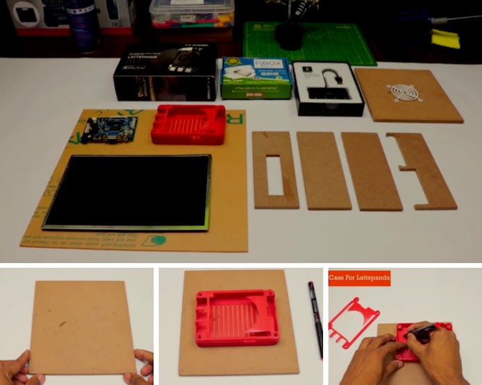
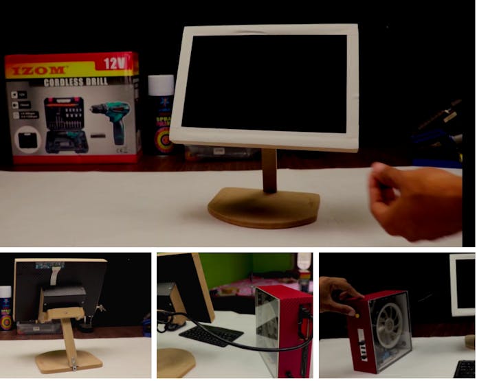
Step 3: Display

This 7-inch LCD monitor with a high resolution of 1024 × 600 pixels supports the operation of the keys and the remote control. It is protected by a box with a support that is made of high-quality black acrylic.
The monitor will support different video input interfaces such as HDMI, VGA and AV (CVBS). In addition, an HDMI cable is included so you can start the screen quickly and conveniently. With the keys on the monitor backward, you can choose to control the screen by pressing the keys or use the remote control "adjust its contrast or color. It is designed with fixing holes in the back, which support the assembly of Raspberry Pi 3 model B, 2 model B, 1 model B + / A + / B, etc.
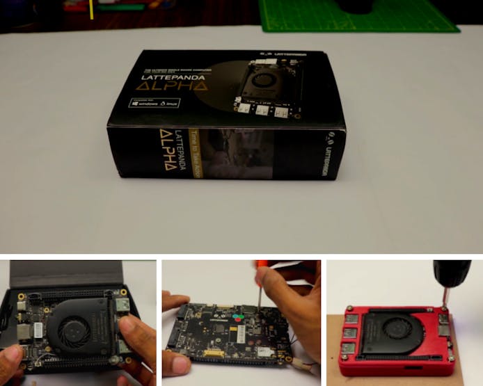
Step 4: Assemble the CPU

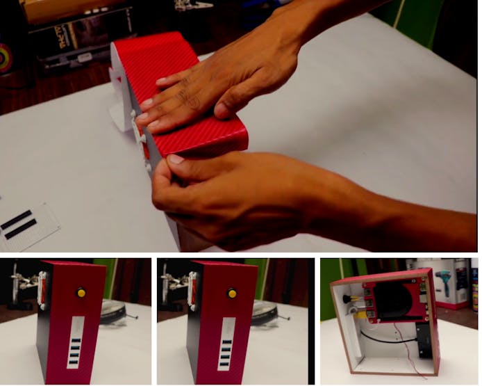
Step 5:

Next, grab your fresh-out-of-the-box LattePanda Alpha 864s and SSD memory card. Attached the SSD card to the LattePanda board as shown.
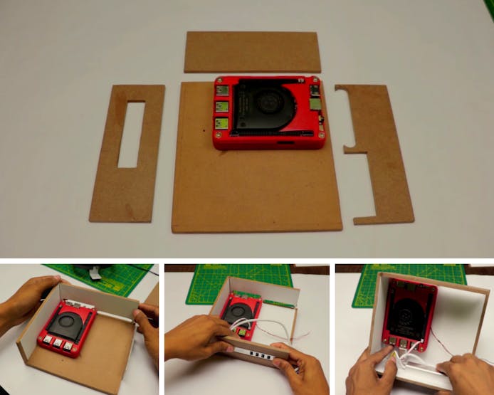
Now mount the LattePanda board (and SSD memory) inside the computer tower casing. Refer to the video to ensure you position the LattePanda correctly.
Step 6: Fan and Lighting
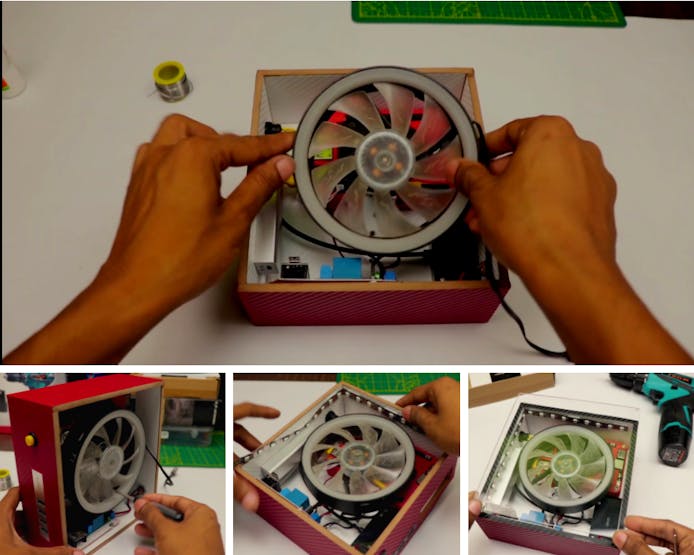
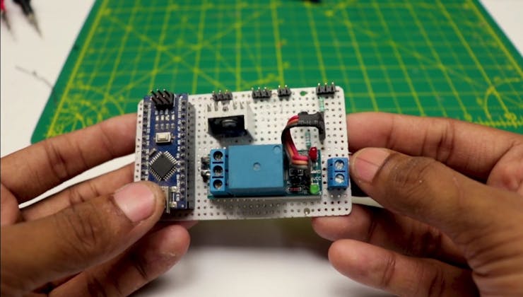
Once complete, the next step is to add some RGB LED strip lighting and RGB fan to give the computer tower some added coolness. With the strip lighting in place, wire up to the Arduino Nano, as shown.
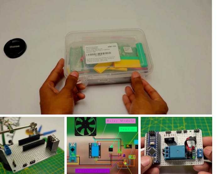
Step 7: LIGHTING CONTROLLER
_QmuG8bCHUy.jpg?auto=compress%2Cformat&w=740&h=555&fit=max)
Nextpcb are also sponsor of this project. Nextpcb, is the one of the largest PCB prototype enterprise in China and a high-tech manufacturer specializing in quick PCB prototype and small-batch PCB production. You can order a minimum of 5 PCBs for just $0 it mean 1st order is free for makers. To get the PCB manufactured simply login Nextpcb.com upload the.zip of the gerber files or you can also drag and drop the.zip files. After uploading the zip file, you’ll see success message at the bottom if the file is successfully uploaded.
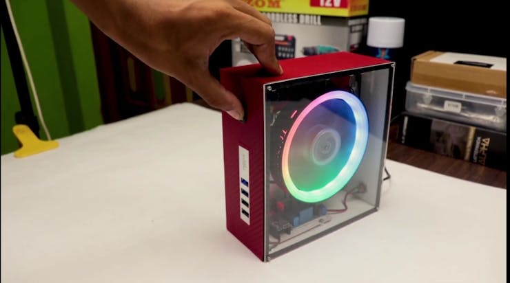
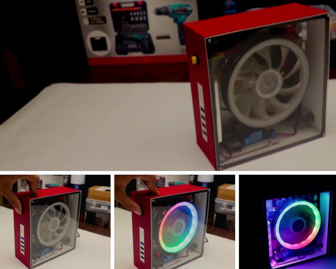
Your tiny PC is pretty much finished at this point. Now re-attach the perspex side panel to complete the tower assembly.
Your tiny PC is pretty much finished at this point. Now re-attach the perspex side panel to complete the tower assembly.
Step 9: Monitor
The last stage is to assemble the monitor. Take your 10.1 inches (25.7cm) display and mount inside the monitor
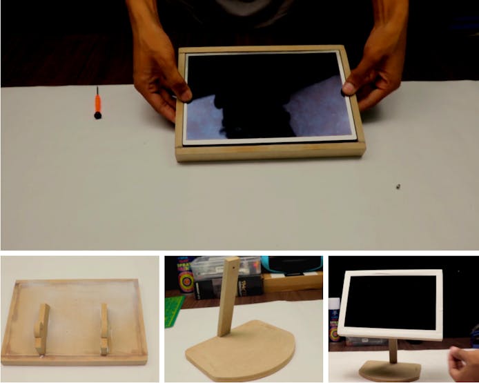
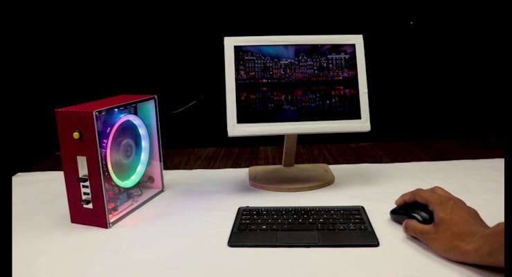
Now simply connect the ISP monitor to the main tower, plug in the power for the LattePanda board and fire her up.Finally, simply sit back and enjoy your masterpiece! Well done you
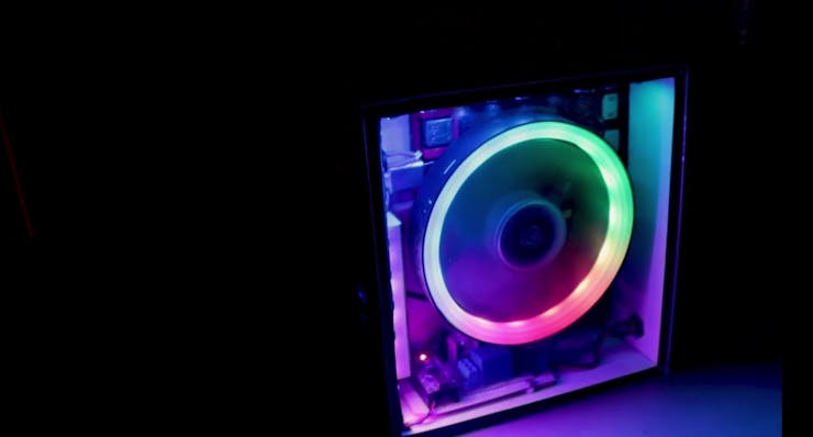
Step 10: Enjoy !

Power on PC and enjoy your portable PC.
Code
#include "FastLED.h"
// How many leds in your strip?
#define NUM_LEDS 8
// For led chips like Neopixels, which have a data line, ground, and power, you just
// need to define DATA_PIN.  For led chipsets that are SPI based (four wires - data, clock,
// ground, and power), like the LPD8806 define both DATA_PIN and CLOCK_PIN
#define DATA_PIN 3
#define CLOCK_PIN 13
// Define the array of leds
CRGB leds[NUM_LEDS];
void setup() {
     // Uncomment/edit one of the following lines for your leds arrangement.
     // FastLED.addLeds<TM1803, DATA_PIN, RGB>(leds, NUM_LEDS);
     // FastLED.addLeds<TM1804, DATA_PIN, RGB>(leds, NUM_LEDS);
     // FastLED.addLeds<TM1809, DATA_PIN, RGB>(leds, NUM_LEDS);
     // FastLED.addLeds<WS2811, DATA_PIN, RGB>(leds, NUM_LEDS);
     // FastLED.addLeds<WS2812, DATA_PIN, RGB>(leds, NUM_LEDS);
     // FastLED.addLeds<WS2812B, DATA_PIN, RGB>(leds, NUM_LEDS);
 	  FastLED.addLeds<NEOPIXEL, DATA_PIN>(leds, NUM_LEDS);
     // FastLED.addLeds<APA104, DATA_PIN, RGB>(leds, NUM_LEDS);
     // FastLED.addLeds<UCS1903, DATA_PIN, RGB>(leds, NUM_LEDS);
     // FastLED.addLeds<UCS1903B, DATA_PIN, RGB>(leds, NUM_LEDS);
     // FastLED.addLeds<GW6205, DATA_PIN, RGB>(leds, NUM_LEDS);
     // FastLED.addLeds<GW6205_400, DATA_PIN, RGB>(leds, NUM_LEDS);
     // FastLED.addLeds<WS2801, RGB>(leds, NUM_LEDS);
     // FastLED.addLeds<SM16716, RGB>(leds, NUM_LEDS);
     // FastLED.addLeds<LPD8806, RGB>(leds, NUM_LEDS);
     // FastLED.addLeds<P9813, RGB>(leds, NUM_LEDS);
     // FastLED.addLeds<APA102, RGB>(leds, NUM_LEDS);
     // FastLED.addLeds<DOTSTAR, RGB>(leds, NUM_LEDS);
     // FastLED.addLeds<WS2801, DATA_PIN, CLOCK_PIN, RGB>(leds, NUM_LEDS);
     // FastLED.addLeds<SM16716, DATA_PIN, CLOCK_PIN, RGB>(leds, NUM_LEDS);
     // FastLED.addLeds<LPD8806, DATA_PIN, CLOCK_PIN, RGB>(leds, NUM_LEDS);
     // FastLED.addLeds<P9813, DATA_PIN, CLOCK_PIN, RGB>(leds, NUM_LEDS);
     // FastLED.addLeds<APA102, DATA_PIN, CLOCK_PIN, RGB>(leds, NUM_LEDS);
     // FastLED.addLeds<DOTSTAR, DATA_PIN, CLOCK_PIN, RGB>(leds, NUM_LEDS);
}
void loop() {
 // Turn the LED on, then pause
 leds[0] = CRGB::Red;
 FastLED.show();
 delay(500);
 // Now turn the LED off, then pause
 leds[0] = CRGB::Black;
 FastLED.show();
 delay(500);
}
This article was first published on Hackster, on May 11, 2021
cr: https://www.hackster.io/diyprojectslab/how-to-make-a-mini-pc-for-gaming-49a378
Author: Raushan kr.


