ESP32-C3 LCD Kit - RGB LED Brightness & Random Color Using Visual Programming

In this Visuino project, you will learn how to use the ESP32-C3 LCD kit to control an RGB LED’s brightness with a rotary encoder. Turning the encoder adjusts the brightness in steps from 0 to 1 with 0.1 increments, and the current brightness level is shown directly on the LCD display. Pressing the encoder’s button instantly sets a random LED color, making the project both fun and interactive.
This tutorial is perfect for learning how to:
Configure and Use the rotary encoder on ESP32-C3Display live brightness values on the LCD screenRandomize LED colors with a simple button pressUse Visuino Visual Programming to quickly design interactive IoT projectsBring your ESP32-C3 LCD kit to life with this engaging RGB LED brightness controller!
Watch the Video!
Step 1: What You Will Need

Step 2: Start Visuino, and Select the ESP32-C3 LCD Kit Board Type

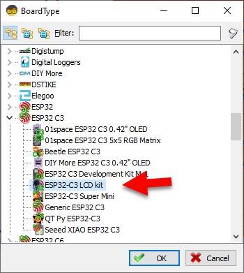
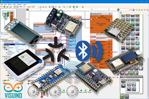
Start Visuino as shown in the first picture Click on the "Tools" button on the Arduino component (Picture 1) in Visuino When the dialog appears, select "ESP32-C3 LCD kit" as shown on Picture 2
Step 3: In Visuino Add Components
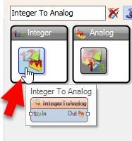
Add Integer To Analog component
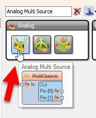
Add Analog Multi Source component
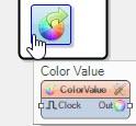
Add Color Value component
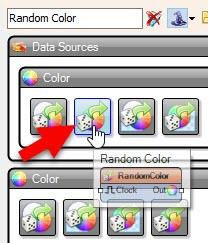
Add Random Color component
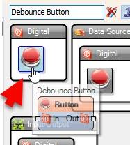
Add DebounceButton component
Step 4: In Visuino Set Components


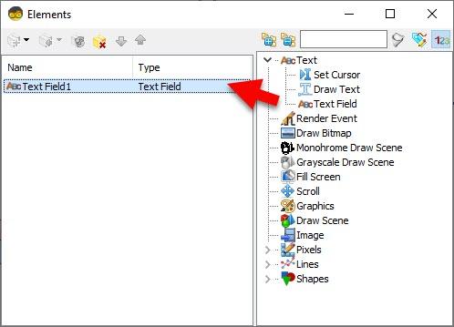
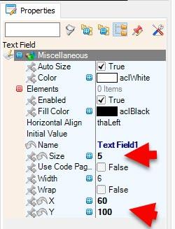

Select "ESP32-C3 LCD kit" board and in the properties window select "Modules" > "RGB LED" > "Brightness" , click on the pin icon and select "Float SinkPin"Select "ESP32-C3 LCD kit" board and in the properties window select "Modules" > "Display" > "Elements" , click on the 3 dots button and in the Elements window drag "Text Field" to the left side and in the properties window set "Size" to 5, "X" to 60 and "Y" to 100Select "ESP32-C3 LCD kit" board and in the properties window set "Rotary Encoder" > "Max" > "Value" to 10 and "Roll Over" to False, and "Min" > "Value" to 0 and "Roll Over" to False.
Step 5: In Visuino Connect Components
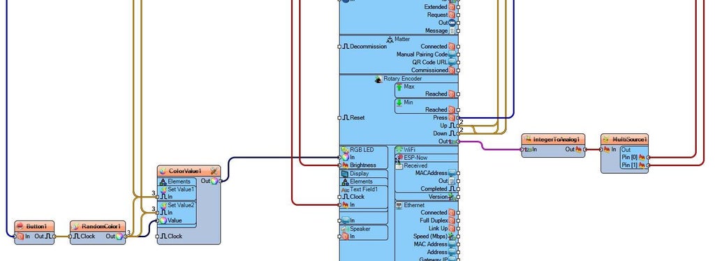
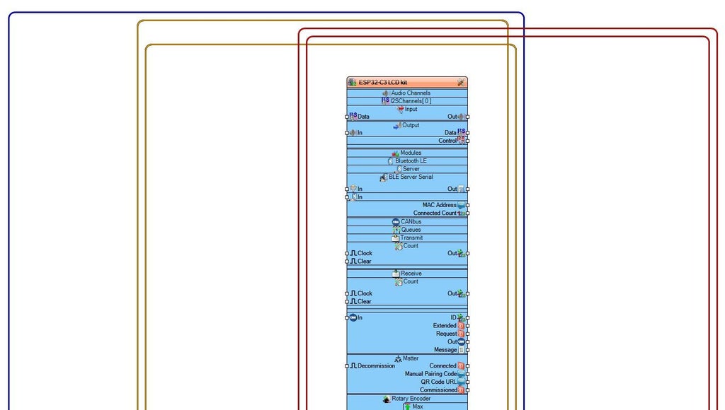
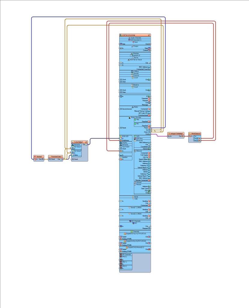
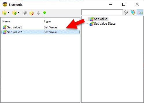
Connect "ESP32-C3 LCD kit" > "Rotary Encoder" Pin [Out] to "IntegerToAnalog1" Pin [In]Connect "IntegerToAnalog1" Pin [Out] to "MultiSource1" Pin [In]Connect "MultiSource1" Pin [0] to "ESP32-C3 LCD kit" > "RGB LED" Pin [Brightness]Connect "MultiSource1" Pin [0] to "ESP32-C3 LCD kit" > "Display" > "Text Field1" Pin [In]Connect "ESP32-C3 LCD kit" > "Rotary Encoder" Pin [Press] to "Button1" Pin [In]Connect "Button1" pin [Out] "RandomColor1" Pin [Clock]Connect "RandomColor1" Pin [Out] "ColorValue1" > "Set Value2" Pin [Value]Connect "RandomColor1" Pin [Out] "ColorValue1" > "Set Value2" Pin [In]Connect "RandomColor1" Pin [Out] "ColorValue1" > "Set Value1" Pin [In]Connect "ESP32-C3 LCD kit" > "Rotary Encoder" Pin [Up] to "ColorValue1" > "Set Value1" Pin [In]Connect "ESP32-C3 LCD kit" > "Rotary Encoder" Pin [Down] to "ColorValue1" > "Set Value1" Pin [In]Connect "ESP32-C3 LCD kit" > "Rotary Encoder" Pin [Up] to "ColorValue1" > "Set Value2" Pin [In]Connect "ESP32-C3 LCD kit" > "Rotary Encoder" Pin [Down] to "ColorValue1" > "Set Value2" Pin [In]Connect "ColorValue1" Pin [Out] to "ESP32-C3 LCD kit" > "RGB LED" Pin [In]
Step 6: Generate, Compile, and Upload the Code
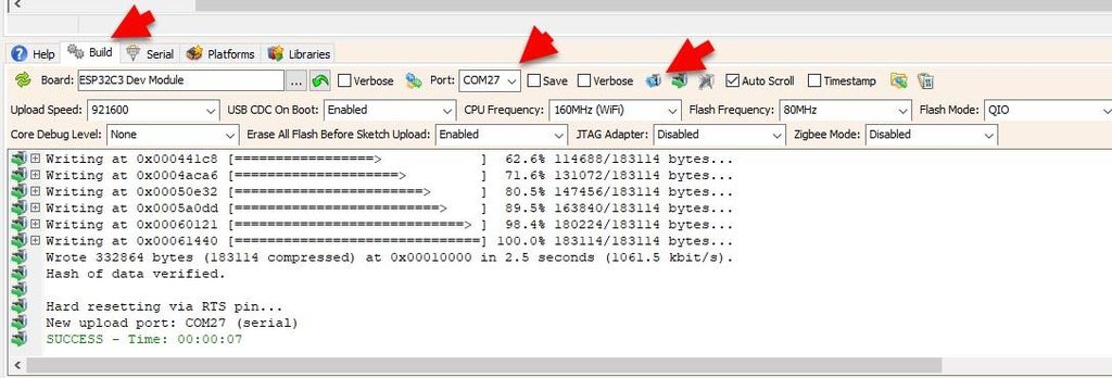
In Visuino, at the bottom click on the "Build" Tab, make sure the correct port is selected, then click on the "Compile/Build and Upload" button.
Step 7: Play
Congratulations! You have completed your project with Visuino. Also attached is the Visuino project, that I created for this tutorial, you can download it here and open it in Visuino: https://www.visuino.eu
Download Visuino file: ESP32-C3 LCD kit-RGB-Brightness.visuino


