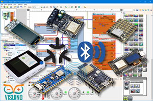
ESP32-C3 LCD Kit – RGB LED Countdown Timer Using Visual Programming

In this Visuino project, you will learn how to use the ESP32-C3 LCD Kit to create a colorful Countdown Timer using a rotary encoder, an LCD display, and an RGB LED. Turn the encoder to set the countdown duration, press the button to start the timer, and watch the countdown update live on the LCD screen. During the countdown, the RGB LED glows green, and when the timer reaches zero, it instantly switches to red, clearly signaling that the time is up — all without writing a single line of code!
This tutorial is perfect for learning how to:
Use the rotary encoder to set and start a countdown timerDisplay live countdown updates on the ESP32-C3 LCD screenControl an RGB LED to show timer status (green for active, red for time-up)Design interactive timing projects with Visuino Visual ProgrammingBring your ESP32-C3 LCD Kit to life with this vibrant and practical RGB LED Countdown Timer project!
Download Project file at the bottom
Watch the Video!
Step 1: What You Will Need

ESP32-C3 LCD kitVisuino program: Download Visuino
Step 2: Start Visuino, and Select the ESP32-C3 LCD Kit Board Type

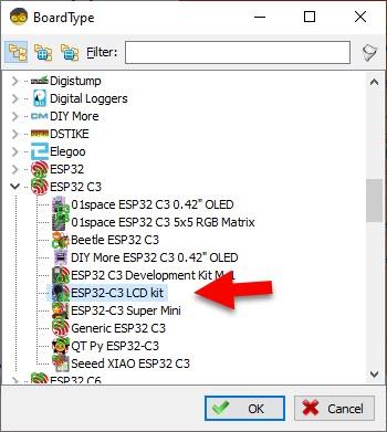
Start Visuino as shown in the first picture Click on the "Tools" button on the Arduino component (Picture 1) in Visuino When the dialog appears, select "ESP32-C3 LCD kit" as shown on Picture 2
Step 3: In Visuino Add Components
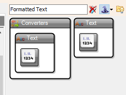
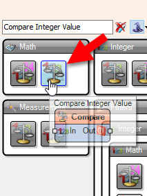

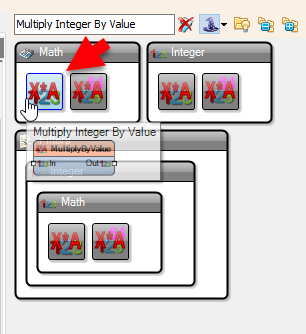
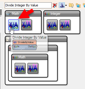
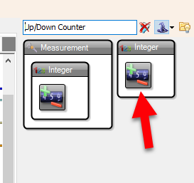
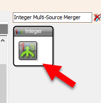
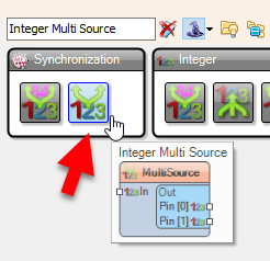
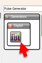
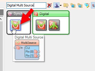
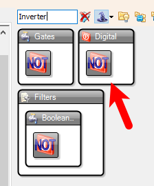
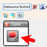
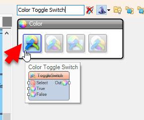
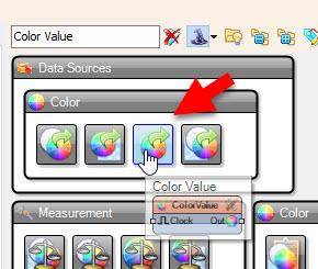
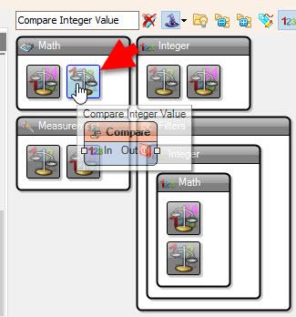
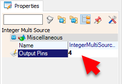
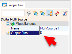
Add "Toggle(T) Flip-Flop" componentAdd "Pulse Generator" componentAdd 3X "Integer Multi Source" componentAdd "Integer Multi-Source Merger" componentAdd "Up/Down Counter" componentAdd "Divide Integer By Value" componentAdd "Multiply Integer By Value" componentAdd "Subtract Integer Value" componentAdd "Formatted Text" componentAdd "Compare Integer Value" componentAdd 2X "Color Value" componentAdd "Color Toggle Switch" component
Step 4: In Visuino Set Components


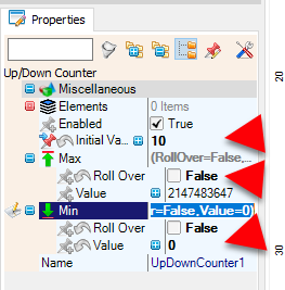


Select ESP32-C3 LCD kit > "Modules" "RotaryEncoderSensor1" and in the properties window select:"Initial Value" and set 10 and set "Max > Roll Over" to False and "Min > Roll Over" to False and Min Value to 0
Also set "Clock Mode" to Rising and "Debounce Interval (mS)" to 5
.
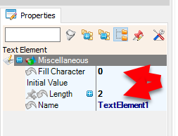
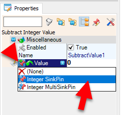
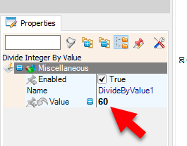
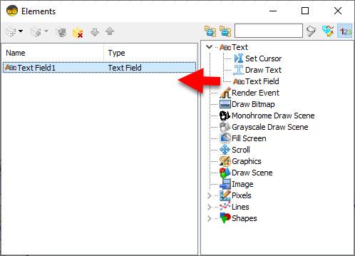
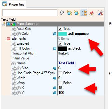
Select "DivideByValue1" and in the properties window set Value to 60Select "MultiplyByValue1" and in the properties window set Value to 60Select "SubtractValue1" and in the properties window select Value and click on the Pin Icon and select "Integer SinkPin"Select "FormattedText1" and in the properties window set "Text" to: %0:%1Double click on "FormattedText1" and in the Elements window drag 2X "Text Element" to the left side and for both in the Properties window set "Fill Character" to 0 and "Length" to 2Select ESP32-C3 LCD kit > "Modules" >"Display" > "Elements" and click on the 3 dots button, and in the Elements window drag "Text Field" to the left side and in the properties window set "Size" to 6 "X" to 45 and "Y" to 100, "Color" to aclTurquoiseSelect "ColorValue1" and set "Value" to ClRedSelect "ColorValue2" and set "Value" to ClGreenStep 5: In Visuino Connect Components
Connect ESP32-C3 LCD kit > Rotary Encoder pin [Press] to "Button1" pin [In]Connect ESP32-C3 LCD kit > Rotary Encoder pin [Out] to "MultiSource2" pin [In]
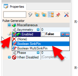
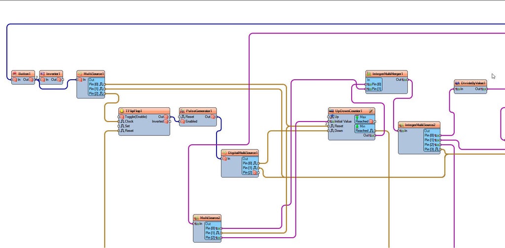
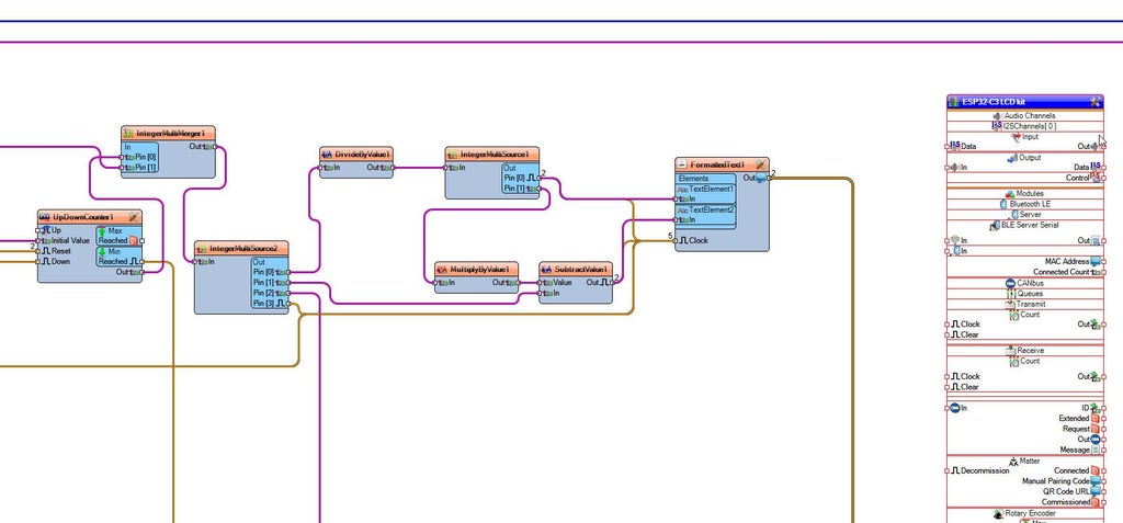
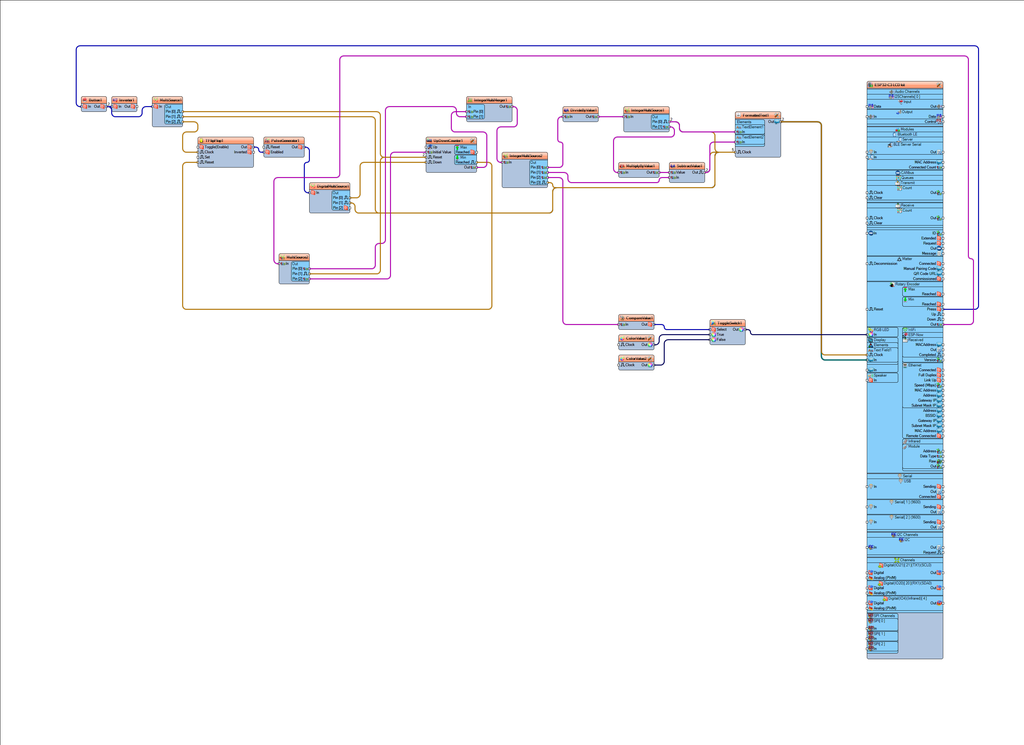
Connect "Button1" pin [Out] to "Inverter1" pin [In]Connect "Inverter1" pin [Out] to "MultiSource1" pin [In]Connect "MultiSource1" pin [Out][0] to "UpDownCounter1" pin [Reset]Connect "MultiSource1" pin [Out][1] to "FormattedText1" pin [Clock]Connect "MultiSource1" pin [Out][2] to "TFlipFlop1" pin [Clock]Connect "DivideByValue1" pin [Out] to "IntegerMultiSource1" pin [In]Connect "IntegerMultiSource1" pin [Out][0] to "FormattedText1" pin [Clock]Connect "IntegerMultiSource1" pin [Out][0] to "FormattedText1" > "TextElement1" pin [In]Connect "IntegerMultiSource1" pin [Out][1] to "MultiplyByValue1" pin [In]Connect "MultiplyByValue1" pin [Out] to "SubtractValue1" pin [Value]Connect "SubtractValue1" pin [Out] to "FormattedText1" pin [Clock]Connect "SubtractValue1" pin [Out] to "FormattedText1" > "TextElement2" pin [In]Connect "FormattedText1" pin [Out] to ESP32-C3 LCD kit > Modules.Display.Elements.Text Field1 pin [In]Connect "FormattedText1" pin [Out] to ESP32-C3 LCD kit > Modules.Display.Elements.Text Field1 pin [Clock]Connect "DisplayOLED1" pin [Out] to "Arduino" > "I2C" pin [In]Connect "UpDownCounter1" pin [Out] to "IntegerMultiMerger1" pin [In][0]Connect "IntegerMultiMerger1" pin [Out] to "IntegerMultiSource2" pin [In]Connect "IntegerMultiSource2" pin [Out][0] to "DivideByValue1" pin [In]Connect "IntegerMultiSource2" pin [Out][1] to "SubtractValue1" pin [In]Connect "IntegerMultiSource2" pin [Out][2] to "CompareValue1" pin [In]Connect "IntegerMultiSource2" pin [Out][3] to "FormattedText1" pin [Clock]Connect "CompareValue1" pin [Out] to "ToggleSwitch1" pin [Select]Connect "ColorValue1" pin [Out] to "ToggleSwitch1" pin [True]Connect "ColorValue2" pin [Out] to "ToggleSwitch1" pin [False]Connect "ToggleSwitch1" pin [Out] to Connect ESP32-C3 LCD kit > Modules.RGB LED pin [In]Connect "PulseGenerator1" pin [Out] to "DigitalMultiSource1" pin [In]Connect "DigitalMultiSource1" pin [Out][0] to "UpDownCounter1" pin [Down]Connect "DigitalMultiSource1" pin [Out][1] to "FormattedText1" pin [Clock]Connect "MultiSource2" pin [Out][0] to "IntegerMultiMerger1" pin [In][1]Connect "MultiSource2" pin [Out][1] to "UpDownCounter1" pin [Reset]Connect "MultiSource2" pin [Out][2] to "UpDownCounter1" pin [InitialValue]Connect "TFlipFlop1" pin [Out] to "PulseGenerator1" pin [Enabled]Connect "UpDownCounter1" pin [MinReached] to "TFlipFlop1" pin [Reset]
Step 6: Generate, Compile, and Upload the Code
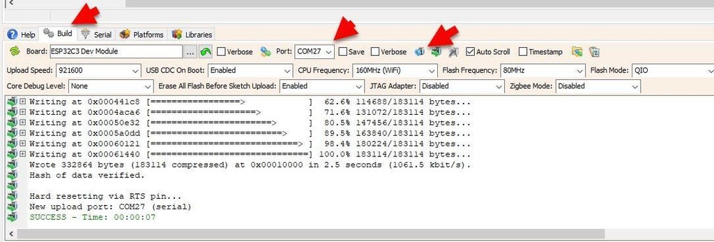
In Visuino, at the bottom click on the "Build" Tab, make sure the correct port is selected, then click on the "Compile/Build and Upload" button.
Step 7: Play
When you power On the ESP32-Kit, the OLED display will show the default countdown time of 00:10.
You can easily adjust the countdown time by rotating the rotary encoder left or right. Once you've set your desired time, simply press the encoder button to start the countdown.
During the countdown, you can pause or resume at any time by pressing the button again.
When the countdown reaches zero, a red LED will turn ON to signal that the time is up.
During the countdown, the RGB LED glows green, and when the timer reaches zero, it instantly switches to red, clearly signaling that the time is up
Congratulations! You have completed your project with Visuino. Also attached is the Visuino project, that I created for this Instructable, you can download it and open it in Visuino: https://www.visuino.com


