
Arduino RP2040 or Raspberry Pi Pico W or ESP32 based mobile robot with on-board pan & tilt camera can be controlled remotely from host PC.

Things used in this project
Hardware components
Software apps and online services
Computer Aided Simulation Program (CASP)
Story
This project demonstrates how to quickly make a simple WiFi remote controlled 4 wheeled mobile robot that has an on-board WiFi camera mounted on a servos powered pan & tilt assembly. It is manually controlled by the user from host PC through WiFi. Because of the live video from the the on-board camera, the rover need not be in line of sight from the user.
Update: This project now supports Arduino RP2040, Raspberry Pi Pico W and ESP32S platforms. Also, check out our upgraded version of the rover at this link: https://create.arduino.cc/projecthub/aadhuniklabs/arduino-based-wifi-mobile-arm-robot-with-on-board-camera-339af6?ref=user&ref_id=2141062&offset=0
This project uses CASP model based programming tool for complete software implementation. It also uses a custom CASP block (where the source code is available to the user) in the native model. The custom block generates required control signals when user presses certain keys for controlling the movements of the robot. User can take a look at the configuration and source code of the block and learn how to integrate the block in a CASP model along with other blocks. User can go through our video tutorial on how to create a custom block at these links: https://aadhuniklabs.com/casp_res_videos#custom_block,
https://aadhuniklabs.com/casp/casp_web_examples/general/01_custom_logic/doc/index.htm
Procedure
Step 1. Build the hardware as described in 'Hardware Development' section below.
Step 2: Install latest version of CASP from this link: https://aadhuniklabs.com/?page_id=550. Please go through this link: https://aadhuniklabs.com/?page_id=554 for video tutorials on CASP. Please note that CASP version 0.9.5.1 and above is recommended for this project.
Step 3: Download example project on 'Basic Remote Controlled Mobile Robot with on-board camera' at this link https://aadhuniklabs.com/casp-examples/#robotics and follow the steps mentioned in the 'Software Development' section.
Step 4: Some adjustments as described in 'Adjustments' section may be required for tuning the software to match your developed hardware.
Step 5: Finally, keyboard and mouse controls to control the mobile rover are described in Control Methodology section. You may change the code in the 'rc_control' custom block in the native model to modify the control keys as per your taste. Please write to us at https://aadhuniklabs.com/contact for any queries & suggestions related to this project.
Hardware Development
Four DC motors are fitted to a suitable metal base frame along with the wheels. Pan & tilt assembly (fitted with two micro servos) is mounted at suitable location of the base frame (preferably towards rare end of the robot base frame). A 12V battery is mounted below the base frame. Required electronic modules are suitably placed on the base frame and are connected as per the connection diagram shown in 'Schematics' section. Typical arrangement is shown in below figure.
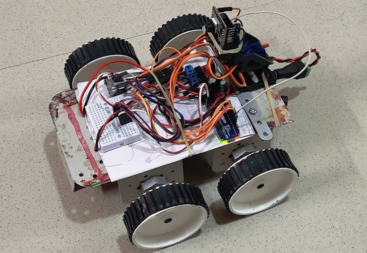
Mobile robot setup
The electronics part consists of Arduino Nano RP2040 Connect or Raspberry Pi Pico W or ESP32 acting as main micro-controller for controlling all required robot functions and communicating with the host PC through the on-board WiFi. The micro-controller generates required PWM signals to control the four wheels through suitable driver circuit. It also controls two servo motors of the camera pan & tilt assembly.
An ESP32 Camera module is mounted on the pan & tilt assembly for capturing live video and stream to the host PC.
Flash light present on the ESP32-CAM module is controlled manually from the host PC via the Arduino Nano RP2040 micro-controller during low light conditions.
A 6V to 12V battery is used to power the entire circuitry on the robot. A 6V/12V to 5V DC step down converter is used to provide required 5V supply to power the micro-controller, servos and ESP32 camera module.
Software Development
A) Configuring ESP32 Camera
ESP32 Camera shall be properly programmed with valid IP address before using it in the project. Please refer to our ESP32-CAM example for details on how to program the module. User may also refer to abundant material available on the internet regarding this subject.
CASP software is used to quickly develop models for Arduino micro-controller target and host PC. As such two models are developed to achieve desired objective.
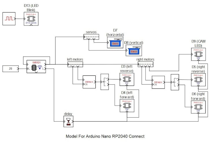
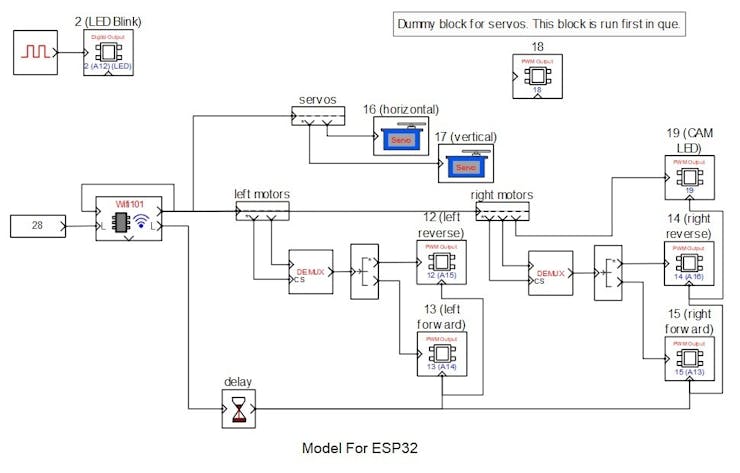
B) Target Model that runs on Arduino Nano RP2040 Connect, Raspberry Pi Pico W and ESP32 consists of
1. Blink logic that indicates the system is running.
2. WiFi101 block that receives required control signals from host PC.
3. PWM and servo blocks that are mapped to the pins of the micro-controller.
4. Time delay block to reset the outputs of the PWM blocks during a communication error or when the host is not connected.

Following are the steps to properly program the target board.
1. Connect the target to the host PC via a USB cable.
2. Note the serial port number to which the board that is connected to the host PC, from the host operating system.
3. Run CASP and load project ‘rc_target_arduino’ for Arduino Nano RP2040 or ‘rc_target_picow’ for Raspberry Pi Pico W target or ‘rc_target_esp32’ for ESP32 target.
4. The WiFi101 block WiFi is set to Station mode. User may need to enter SSID and password of the network to which the device should be connected. The Local IP address parameter shall be configured as assigned by the network DHCP client of the network.
5. From CASP, open Home->Simulation->Setup Simulation Parameters menu item. Under Target HW->General tabs set ‘Target Hardware Programmer Port’ parameter to the serial port to which the board is connected.
6. Build the model and program the board by clicking on Run button.
C) Native Model that runs on Host PC consists of
1. Camera block that receives live video from the ESP32 Camera. IP address of the ESP32 Camera shall be entered in block parameters of this block.
2. Image display block to display the live video received from the camera. It is also configured to output keyboard and mouse signals.
3. RC control block: It is a custom block that receives keyboard and mouse signals from the image display block and generates suitable control signals for controlling the robot motion and its head (pan & tilt) movements.
4. GPIO blocks that maps to the target model via the WiFi communication channel.
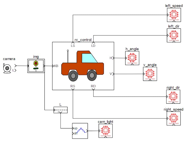
Native model that runs on host PC
Following are the steps to run the native model on the host PC
1. Before continuing, the host PC shall be connected to the same network as the device is connected.
2. Load the ‘rc_native’ project.
3. Click on Home->Simulation->Configure Simulation IO menu item.
4. ‘Configure Simulation Hardware’ window will open. Under Native Nodes and GPIO Device Nodes, change the IP addresses marked in the below figure (by double clicking on the item) to respective local and device IP addresses.
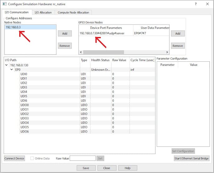
Configure Simulation Hardware window to change IP addresses of native node (host PC) and GPIO device (Arduino RP2040)
5. Click on ‘Connect Device’ button and check the ‘Online Data’ check box. The program should now communicate with the target with cycle time around 30msecs. Target board is now available as endpoint ‘EP0’ to the native model. Native model can use this end point to connect to respective IOs on the target.
6. Click on ‘Save’ button to save the configuration and close the window.
7. Run the model by clicking on the Run button. A simulation panel window should open and communicate with the board.
8. Screen shot of the output simulation panel running on host PC and display the camera live video is shown below.
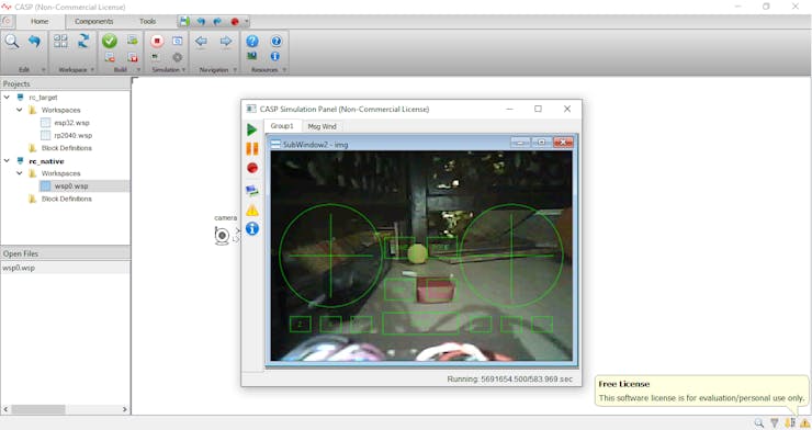
Simulation Panel Window with on-board camera live video
Adjustments
1. Wheel motor connections may be reversed to get forward or backward movement when W and S are pressed.
2. Logics for generating forward and reverse motor rotation are developed to match with the motor driver IC i.e.TA6586 used in the project. User may modify the logics suitably if other driver IC is used.
3. Servo motors may require some alignments to face towards robot forward direction for the default angle specified in the rc_control block parameters.
4. Base speed, speed limits and other parameters related to the navigation are adjustable from the rc_control block parameters.
Control Methodology
1. The simulation panel window shown above accepts keyboard & mouse inputs when it is active.
2. User can use the keyboard keys W – to move forward, S – to move backward, A – to rotate left on center and D – to rotate right on center.
3. Combination of keys W/S & A/D can be used to take left and right turns while moving forward or backward.
4. Speed can be adjusted by using Page Up & Page Down keys.
5. Vertical and horizontal servo angles (from -90 to +90 deg) for head position control can be controlled by mouse movements.
6. Key ‘G’ is used to position both servos at default angle.
7. Key 'L' is used to ON/OFF the flash LED light of the ESP32 camera.
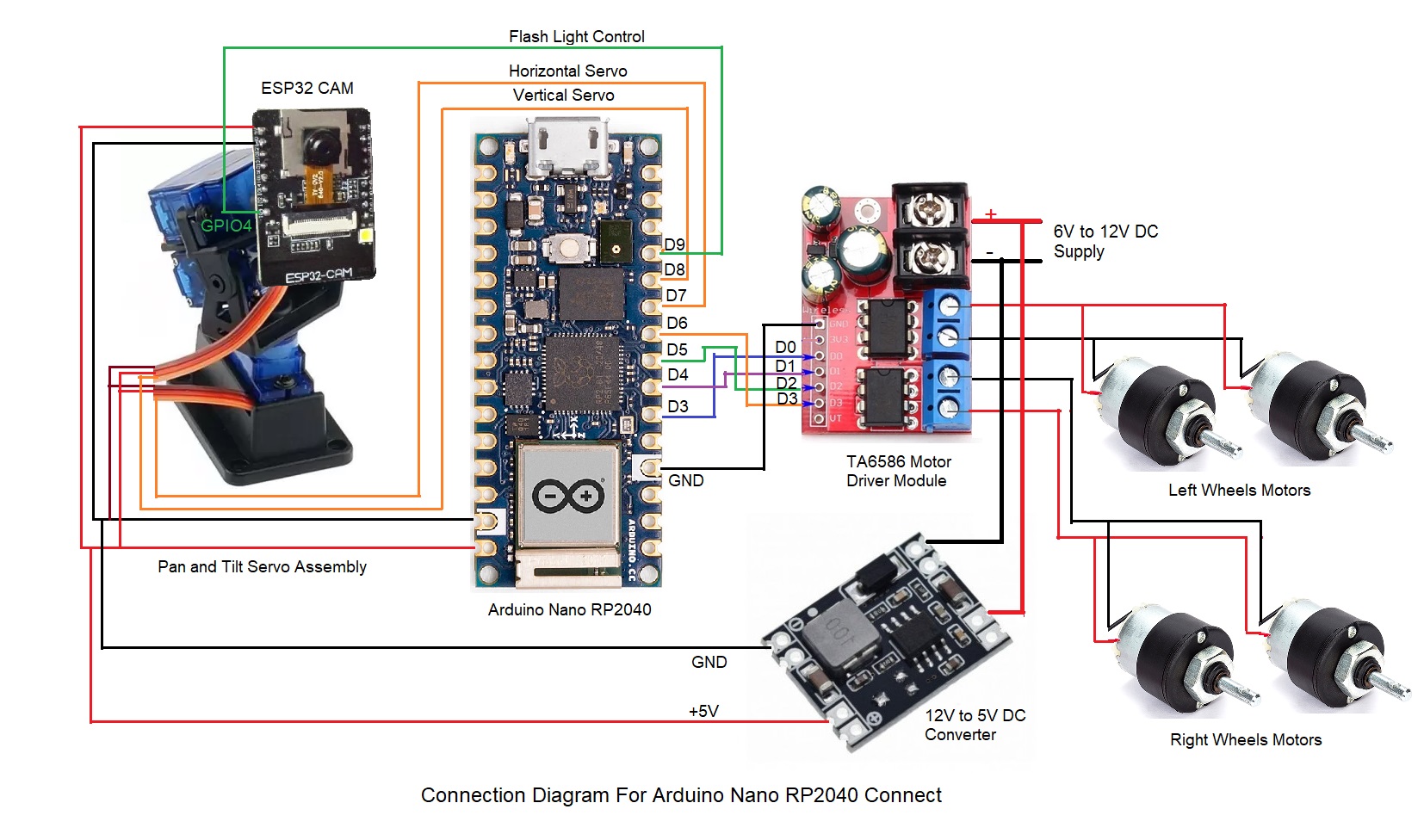
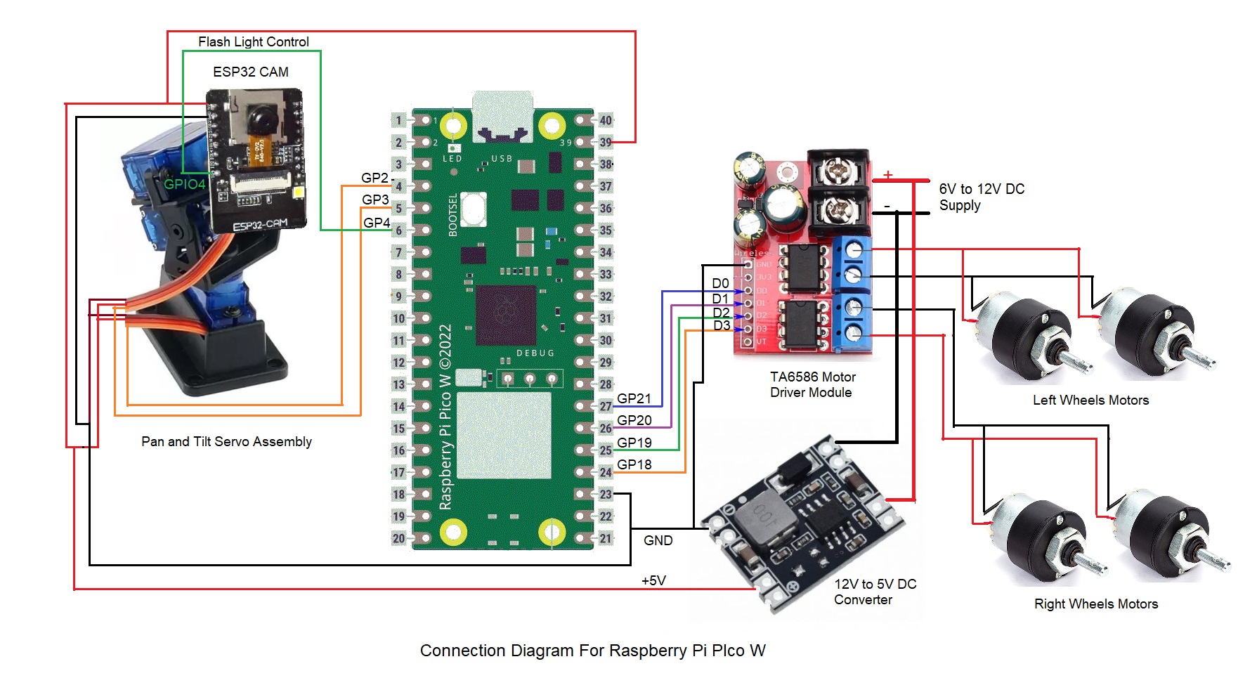
Schematics
Connection Diagram for Arduino Nano RP2040 Connect
Connection Diagram for Raspberry Pi Pico W
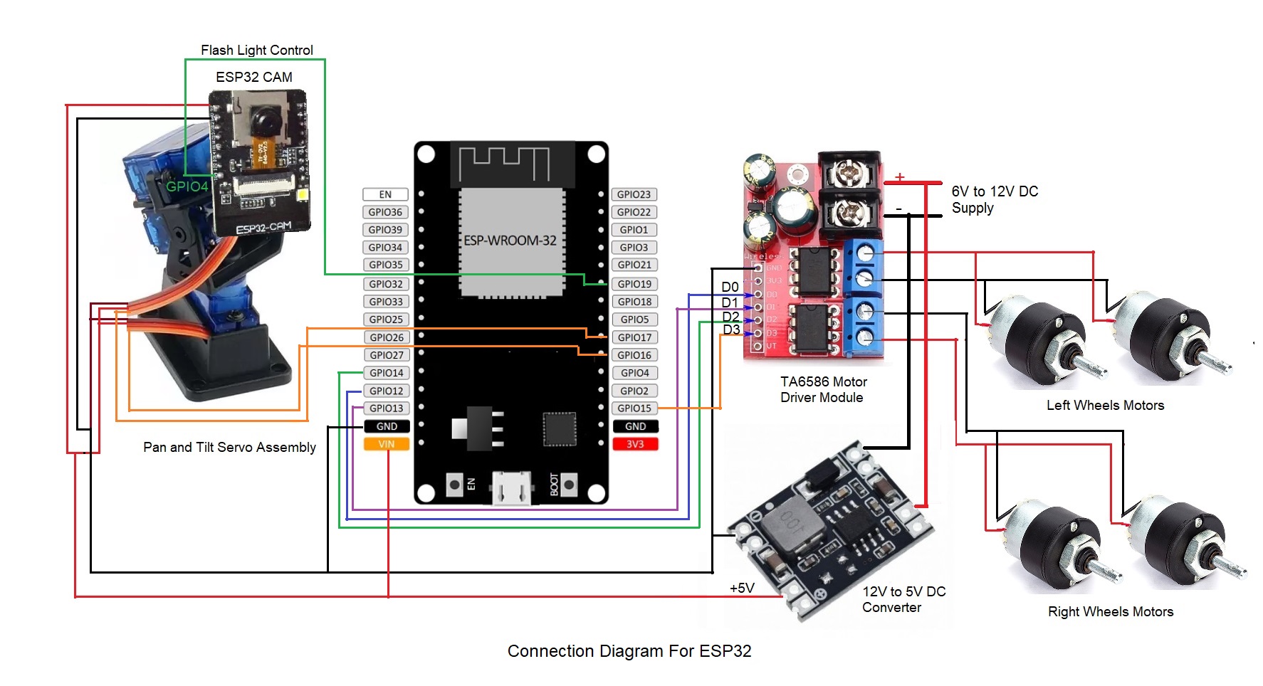
Connection Diagram for ESP32S
Code
Source Code For Remote Control Car custom block used in the Native Model of this project
C/C++
This custom block generates required control signals when user presses certain keys for controlling the movements of the robot. User can take a look at the configuration and source code of the block and learn how to integrate the block in a CASP model along with other blocks.
//Header file code

/************************CASP_COPYRIGHT**********************************
** Copyright (c) AadhunikLabs. All rights reserved.
** This file is part of CASP.
** Licensees holding valid licenses may use this file in accordance
** with the license agreement provided with the software.
*************************************************************************/
#ifndef REMCARMANUAL927823855_H
#define REMCARMANUAL927823855_H

#include "sim_common_definitions.h"

#define UPDATE_INTERVAL 10UL//in milli secs

class SHARED_LIB_TYPE RemCarManual927823855
{
public:
    RemCarManual927823855();
    ~RemCarManual927823855();
    void Initialize(const volatile BLOCK_CONSTRUCTOR_PARAM_STRUCT *arg);
    void PreRun(const volatile GLOBAL_PRERUN_PARAM_STRUCT *arg, _INT32 *kb_in, _FLOAT *l_speed_out, _INT32 *l_dir_out, _FLOAT *r_speed_out, _INT32 *r_dir_out, _FLOAT *h_angle_out, _FLOAT *v_angle_out);
    void Run(const volatile GLOBAL_RUN_PARAM_STRUCT *arg, _INT32 *kb_in, _FLOAT *l_speed_out, _INT32 *l_dir_out, _FLOAT *r_speed_out, _INT32 *r_dir_out, _FLOAT *h_angle_out, _FLOAT *v_angle_out);
    void RunPlotStep(const volatile GLOBAL_RUN_PARAM_STRUCT *arg, _INT32 *kb_in, _FLOAT *l_speed_out, _INT32 *l_dir_out, _FLOAT *r_speed_out, _INT32 *r_dir_out, _FLOAT *h_angle_out, _FLOAT *v_angle_out);
    void PostRun(const volatile GLOBAL_POSTRUN_PARAM_STRUCT *arg, _INT32 *kb_in, _FLOAT *l_speed_out, _INT32 *l_dir_out, _FLOAT *r_speed_out, _INT32 *r_dir_out, _FLOAT *h_angle_out, _FLOAT *v_angle_out);
public:
    //port variable declaration
    //port dimension and size declaration
    //block internal parameter variable declaration
    _FLOAT base_speed, min_speed, max_speed, speed_step;
    _FLOAT rotate_speed;
    _FLOAT head_speed[2];
    _FLOAT head_hangle[3], head_vangle[3];//min,max,def
    _BYTE head_control;
    //block internal initial condition variable declaration
private:
    _FLOAT rotate_speed_inc, rotate_speed_dec;
    _BOOLEAN m_head_speed_reverse[2];
    int m_init_mouse_pos[2];//during last head movement
    int m_prev_mouse_pos[2];//prev position
    _UINT64 m_update_count;
};

#endif

//CPP file code

/************************CASP_COPYRIGHT**********************************
** Copyright (c) AadhunikLabs. All rights reserved.
** This file is part of CASP.
** Licensees holding valid licenses may use this file in accordance
** with the license agreement provided with the software.
*************************************************************************/
#include "RemCarManual927823855.h"
#include "math.h"
#include "simcode.h"

RemCarManual927823855::RemCarManual927823855(){
}

RemCarManual927823855::~RemCarManual927823855(){
}

void RemCarManual927823855::Initialize(const volatile BLOCK_CONSTRUCTOR_PARAM_STRUCT *arg){
}

void RemCarManual927823855::PreRun(const volatile GLOBAL_PRERUN_PARAM_STRUCT *arg, _INT32 *kb_in, _FLOAT *l_speed_out, _INT32 *l_dir_out, _FLOAT *r_speed_out, _INT32 *r_dir_out, _FLOAT *h_angle_out, _FLOAT *v_angle_out){
    m_init_mouse_pos[0] = kb_in[257];
    m_init_mouse_pos[1] = kb_in[258];
    m_prev_mouse_pos[0] = kb_in[257];
    m_prev_mouse_pos[1] = kb_in[258];
    //
    *l_speed_out = 0;
    *l_dir_out = 1;
    *r_speed_out = 0;
    *r_dir_out = 1;
    //
    *v_angle_out = head_vangle[2];
    *h_angle_out = head_hangle[2];
    //
    rotate_speed_inc = 1.0f+(rotate_speed/100.0f);
    rotate_speed_dec = 1.0f-(rotate_speed/100.0f);
    speed_step = speed_step/100.0f;
    m_update_count = arg->rt_clk_tick;
    //
    for(int i=0; i<2; ++i)
    {
        m_head_speed_reverse[i] = (head_speed[i] < 0)?1:0;
        head_speed[i] = (head_speed[i] < 0)?-head_speed[i]:head_speed[i];
    }
}

void RemCarManual927823855::Run(const volatile GLOBAL_RUN_PARAM_STRUCT *arg, _INT32 *kb_in, _FLOAT *l_speed_out, _INT32 *l_dir_out, _FLOAT *r_speed_out, _INT32 *r_dir_out, _FLOAT *h_angle_out, _FLOAT *v_angle_out){
    if(arg->rt_clk_tick-m_update_count < UPDATE_INTERVAL*1000)
        return;
    m_update_count = arg->rt_clk_tick;
    //
    *l_speed_out = 0;
    *r_speed_out = 0;
    *l_dir_out = 1;
    *r_dir_out = 1;
    //adjust speed
    if(kb_in[34])//pg down
    {
        _FLOAT val = base_speed * (1.0f-speed_step);
        if(val > min_speed)
            base_speed = val;
    }
    else if(kb_in[33])//pg up
    {
        _FLOAT val = base_speed * (1.0f+speed_step);
        if(val < max_speed)
            base_speed = val;
    }
    //forward and backward
    if(kb_in[87])//W-forward
    {
        *l_speed_out = *r_speed_out = base_speed;
        if(kb_in[65])//A-left
        {
            *l_speed_out *= rotate_speed_dec;
            *r_speed_out *= rotate_speed_inc;
        }
        else if(kb_in[68])//D-right
        {
            *l_speed_out *= rotate_speed_inc;
            *r_speed_out *= rotate_speed_dec;
        }
        //check limits
        if(*l_speed_out > max_speed)
            *l_speed_out = max_speed;
        else if(*l_speed_out < min_speed)
            *l_speed_out = min_speed;
        if(*r_speed_out > max_speed)
            *r_speed_out = max_speed;
        else if(*r_speed_out < min_speed)
            *r_speed_out = min_speed;
        //
        *l_dir_out = 1;
        *r_dir_out = 0;
    }
    else if(kb_in[83])//S-reverse
    {
        *l_speed_out = *r_speed_out = base_speed;
        if(kb_in[65])//A-left
        {
            *l_speed_out *= rotate_speed_dec;
            *r_speed_out *= rotate_speed_inc;
        }
        else if(kb_in[68])//D-right
        {
            *l_speed_out *= rotate_speed_inc;
            *r_speed_out *= rotate_speed_dec;
        }
        //check limits
        if(*l_speed_out > max_speed)
            *l_speed_out = max_speed;
        else if(*l_speed_out < min_speed)
            *l_speed_out = min_speed;
        if(*r_speed_out > max_speed)
            *r_speed_out = max_speed;
        else if(*r_speed_out < min_speed)
            *r_speed_out = min_speed;
        //
        *l_dir_out = 0;
        *r_dir_out = 1;
    }
    //if no forward or reverse pressed. then rotate on center
    else//if(kb_in[87] == 0 && kb_in[83] == 0)
    {
        if(kb_in[65])//A-left
        {
            *l_speed_out = *r_speed_out = base_speed;
            *l_dir_out = 0;
            *r_dir_out = 0;
        }
        else if(kb_in[68])//D-right
        {
            *l_speed_out = *r_speed_out = base_speed;
            *l_dir_out = 1;
            *r_dir_out = 1;
        }
    }
    //head rotation
    if(head_control == 1)//from mouse
    {
        int x = kb_in[257];
        int y = kb_in[258];
        int diffx = x - m_init_mouse_pos[0];
        int diffy = y - m_init_mouse_pos[1];
        if(diffx != 0)
        {
            //if(x == m_prev_mouse_pos[0])//user stabilized mouse position. move head
            {
                if(kb_in[256] & 0b10)//if right button pressed then only move mouse
                {
                    if(m_head_speed_reverse[0])
                        *h_angle_out += (diffx * head_speed[0] * 0.1);
                    else
                        *h_angle_out -= (diffx * head_speed[0] * 0.1);
                    if(*h_angle_out < head_hangle[0])
                        *h_angle_out = head_hangle[0];
                    else if(*h_angle_out > head_hangle[1])
                        *h_angle_out = head_hangle[1];
                }
                m_init_mouse_pos[0] = x;
            }
        }
        if(diffy != 0)
        {
            //if(y == m_prev_mouse_pos[1])//user stabilized mouse position. move head
            {
                if(kb_in[256] & 0b10)//if right button pressed then only move mouse
                {
                    if(m_head_speed_reverse[1])
                        *v_angle_out -= (diffy * head_speed[1] * 0.1);
                    else
                        *v_angle_out += (diffy * head_speed[1] * 0.1);
                    if(*v_angle_out < head_vangle[0])
                        *v_angle_out = head_vangle[0];
                    else if(*v_angle_out > head_vangle[1])
                        *v_angle_out = head_vangle[1];
                }
                m_init_mouse_pos[1] = y;
            }
        }
        m_prev_mouse_pos[0] = x;
        m_prev_mouse_pos[1] = y;
    }
    else//from arrow keys
    {
        //37-left, 38-up,39-right,40-bottom
        if((kb_in[37] && m_head_speed_reverse[0] == false) || (kb_in[39] && m_head_speed_reverse[0] == true))
        {
            *h_angle_out += (head_speed[0]);
            if(*h_angle_out > head_hangle[1])
                *h_angle_out = head_hangle[1];
        }
        else if((kb_in[39] && m_head_speed_reverse[0] == false) || (kb_in[37] && m_head_speed_reverse[0] == true))
        {
            *h_angle_out += (-head_speed[0]);
            if(*h_angle_out < head_hangle[0])
                *h_angle_out = head_hangle[0];
        }
        if((kb_in[38] && m_head_speed_reverse[1] == false) || (kb_in[40] && m_head_speed_reverse[1] == true))
        {
            *v_angle_out += (-head_speed[1]);
            if(*v_angle_out < head_vangle[0])
                *v_angle_out = head_vangle[0];
        }
        else if((kb_in[40] && m_head_speed_reverse[1] == false) || (kb_in[38] && m_head_speed_reverse[1] == true))
        {
            *v_angle_out += (head_speed[1]);
            if(*v_angle_out > head_vangle[1])
                *v_angle_out = head_vangle[1];
        }
    }
    //center horizontal and vertical heads when G is pressed
    if(kb_in[71])
    {
        *h_angle_out = head_hangle[2];
        *v_angle_out = head_vangle[2];
    }
}

void RemCarManual927823855::RunPlotStep(const volatile GLOBAL_RUN_PARAM_STRUCT *arg, _INT32 *kb_in, _FLOAT *l_speed_out, _INT32 *l_dir_out, _FLOAT *r_speed_out, _INT32 *r_dir_out, _FLOAT *h_angle_out, _FLOAT *v_angle_out){
    Run(arg, kb_in, l_speed_out, l_dir_out, r_speed_out, r_dir_out, h_angle_out, v_angle_out);
}

void RemCarManual927823855::PostRun(const volatile GLOBAL_POSTRUN_PARAM_STRUCT *arg, _INT32 *kb_in, _FLOAT *l_speed_out, _INT32 *l_dir_out, _FLOAT *r_speed_out, _INT32 *r_dir_out, _FLOAT *h_angle_out, _FLOAT *v_angle_out){
}
The article was first published in hackster, August 25, 2022
cr: https://www.hackster.io/aadhuniklabs/a-simple-wifi-controlled-mobile-robot-with-pan-tilt-camera-ea6da1
author: Aadhuniklabs


