
This project uses oneM2M and ESP32 to create a smart traffic light system using cellular based IoT with the Nordic Thingy:91
Things used in this project
Hardware components
Hand tools and fabrication machines
10 Pc. Jumper Wire Kit, 5 cm Long
Breadboard, 8 mm x 35 mm
Story
Introduction
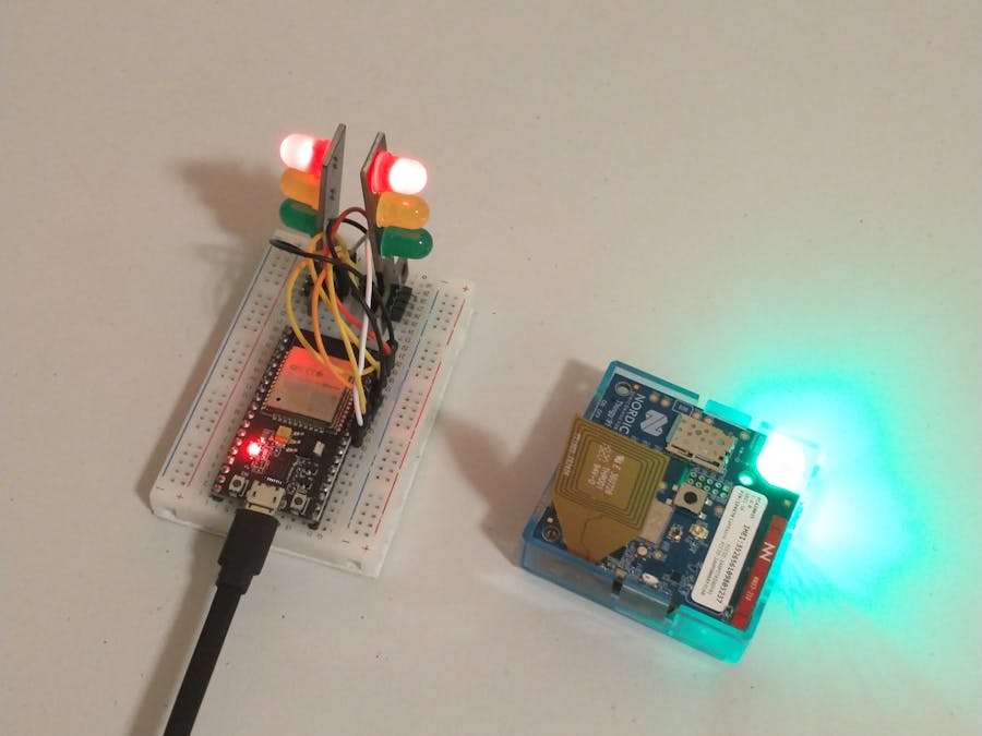
In this project, we have used oneM2M, Nordic Semiconductor's Thingy:91, and an ESP32 to create IoT-controlled traffic lights that can be tested through a graphical Upper Tester interface.
Traffic lights are simple devices to control and serve as an example of the revolutionary power of using IoT for Smart Cities.
The Upper Tester program allows our traffic light Application Entities (AEs) to be tested before deployment. Smart City IoT applications are parts of critical infrastructure and must undergo a thorough examination and testing before deployment. Our Upper Tester program is an example of how to test IoT devices using oneM2M.
Design Features and Relation to Technical Specifications
IoT devices pack a variety of capabilities in small, low-power devices. Our project utilizes the Thingy:91 by Nordic Semiconductor. The Thingy:91 contains two microprocessors that provide both processing and connectivity capabilities.
The main application processor, the nRF9160 SiP, is where our complex Application Entity program will run, and it contains an LTE modem for connecting to the Internet.
Connected to the nRF9160 through two UART ports is a nRF52840 SoC. This nRF52840 provides Bluetooth Low Energy (BLE) connectivity, and enables us to scan, pair, and communicate over BLE to our ESP32's. We've named the program running on the nRF52840 the "AE Backend." This AE backend is not intelligent and is fully controlled by the AE program running on the nRF9160.
It can be confusing to understand the split between both chips, so we've created the below diagram to better illustrate the interconnection at play:
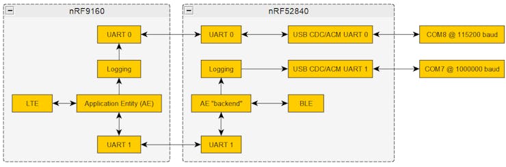
Communication flow between Thingy:91 hardware and software components.
Within the nRF9160 is an LTE modem, and because of this, it is responsible for establishing the LTE connection, polling the CSE for notifications, and sending UPDATE requests to the CSE. The main AE program does not deal with connecting to or sending commands to the ESP32. Instead, it manages the state of the ESP32 by sending command messages to the nRF52840 through the UART1 port.
The nRF52840 is responsible for connecting to the ESP32 over BLE and sending control messages to the ESP32 over BLE. Any commands it receives from the nRF9160 through the UART1 port are sent over BLE to the ESP32.
Because the nRF52840 also contains the USB endpoints, it is also responsible for acting as a “pass-through” from the USB port to the UART port on the nRF9160. This pass-through allows a computer connected via USB to communicate directly to the nRF9160. This pass-through also enables the nRF9160 to be flashed through USB without reflashing the nRF52840.
Material and Component Selection Process
The Thingy:91 was selected as a component as it is what we planned to design the upper tester for since the project's conception. It is a simple IoT device allowing for simultaneous LTE and Bluetooth connections. As for the ESP32, we decided to utilize this due to its widespread use, rich API, Bluetooth capabilities, and cheapness/ease of access. The selection of this component was primarily due to familiarity. There might be better interfaces, but starting the code as soon as possible was the highest priority.
Amazon Web Services (AWS) was selected as the provider for our cloud services, which hosts our web server and the ACME CSE, because of its ease of use and low cost. Although there are other cloud providers available, members of the team were most familiar with AWS, and the cost difference between AWS and other cloud providers is negligible.
How it works
To begin the traffic light demo, ensure that the AMCE CSE is running and the ESP32s corresponding to the Things:91s are powered on. When the Thingy:91 is switched on, it will go through multiple start-up procedures before it is ready to begin polling data from the ACME CSE. First, the Thingy:91 LED will flash blue, indicating that the Thingy:91 is attempting to establish a Bluetooth connection to the ESP32. Second, the Thingy:91 LED will Flash red while the LTE connection established. Once LTE and Bluetooth connections are established, the Thingy:91 LED will flash green. If the Thingy:91 drops its LTE or Bluetooth connection at any point, it will revert to the LED light state it had when establishing that connection. Once the LED on the Thingy:91 is flashing green, it will begin creating the required oneM2M resources it needs on the ACME CSE. The Thingy:91 will first create a unique ACP to identify itself and an AE to identify the intersection that it will control. Under the AE, the Thingy:91 will create a Flex Container to store the Bluetooth connection status, light one status, and light two status. To monitor these values, the Thingy:91 will create a polling channel under the AE and subscribe to the Flex Container, which will monitor the three variables through a polling channel. These resources can be monitored in the ACME CSE.
The second part of the traffic light demo is the web dashboard that allows a user to change the light state of an intersection. Once the Dashboard is connected to the ACME, it will begin monitoring for new intersections to be created. Once a new intersection is created, it will automatically subscribe to it and display it on the dashboard. Once the intersection is displayed on the dashboard, the user can change the light states through the interface that has been created. When an intersection is deleted, the dashboard will automatically delete the interface corresponding to that intersection. Multiple dashboards can be used simultaneously without causing errors in the intersection light states.
Once the traffic light demo is running, the Upper Tester can test the Thingy:91s conformance to oneM2M. To do this, connect the Thingy:91 via USB to the laptop running the Upper Tester. Run the python program, and a window will appear with all functions that can be performed. Before the Upper Tester can run any of the functions, the button labeled “Test On” need to be pressed so that the Thingy:91 enters test mode. Once in test mode, the other functions can be used to test individual actions the Thingy:91 can perform. Once testing is done, the button “Testing off” can be selected to place the Thingy:91 back to standard functionality.
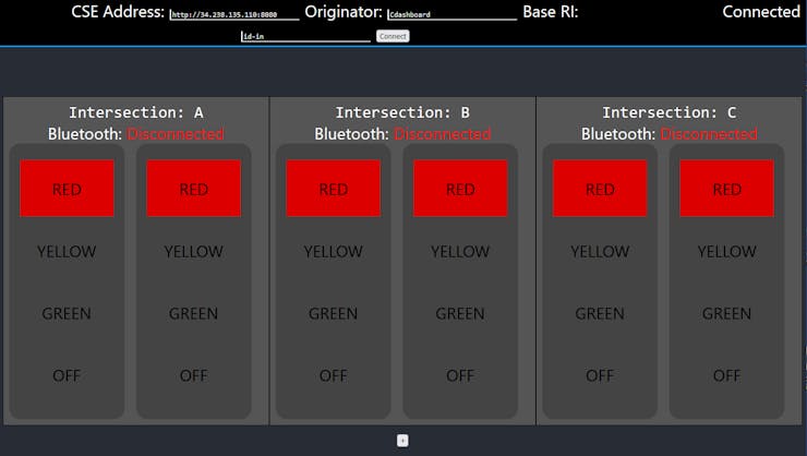
React JS web dashboard for control of the traffic lights.
Design Analysis
As described in above, the interconnection between the nRF52840 and nRF9160 is mainly performed through the UART1 connection. We have designed the software running on the nRF52840 to act as a “puppet” controlled by the nRF9160. The nRF52840 sends notifications to the nRF9160 about events occurring, but it does not control the nRF9160. The following event notifications from the nRF52840 are sent to the nRF9160 over the UART1 port:
CONNECTED – BLE connection to the ESP32 is establishedDISCONNECTED – BLE connection to the ESP32 was lostSCAN_STARTED – The nRF52840 has started scanning for BLE devicesSCAN_STOPPED - The nRF52840 has stopped scanning for BLE devices
The nRF9160 sends the following command messages to the nRF52840 through the UART1 port:
START_SCAN – Start scanning for BLE devicesSTOP_SCAN – Stop scanning for BLE devicesGREEN1 – Set light 1 to greenYELLOW1 – Set light 1 to yellowRED1 – Set light 1 to redOFF1 – Turn light 1 offGREEN2 – Set light 2 to greenYELLOW2 – Set light 2 to yellowRED2 – Set light 2 to redOFF2 – Turn light 2 off
Test Procedure Plan
The most critical component of our testing is modularization of each component, such that each component can be tested individually as well as when integrated together. The main focus of the project is the tester, but we also want to be able to verify that the other components of the AE are also functioning as expected. So far, we have completed the Bluetooth and LTE aspects of both the ESP32 and the Thingy:91, and we created different criteria to verify functionality for all components.
In the case of the ESP32, we were able to verify the Bluetooth control interface via smartphone connection. Rigorous testing was performed to show that the ESP32 would switch the traffic light to the correct color on demand.
In the case of the Thingy:91, we can verify both the Bluetooth and the LTE via a serial terminal in the Arduino IDE, or through PuTTY. After conducting individual testing, we were able to perform integration testing by connecting the Thingy:91 and the ESP32 together, and then visually confirming that the correct lights switched when we sent the corresponding command.
For conformance testing, we created the Upper Tester, which allowed the Thingy:91 to be put in the testing state where specific oneM2M resources could be created and deleted. The Thingy:91 and intersection can be fully deleted, created, and reset with their own commands. It also allows for the retrieval and update of data value to happen specifically when a user request.
After manually performing this, we wrote a Python script to automatically send these commands over serial communication. This script is the foundation of our Upper Tester program. The script has many features, such as being able to generate random input, and provides an interface to users which allows them to easily input their testing protocol.
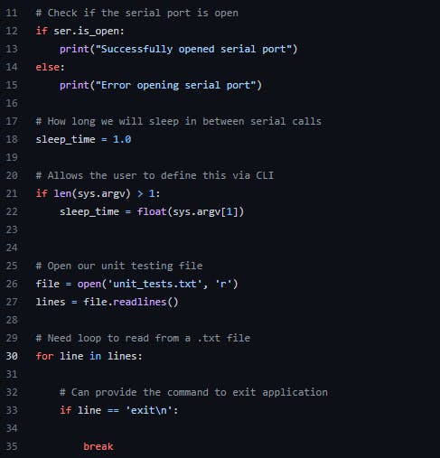
Part of the code for our upper tester
Upper Tester
The Upper Tester is a Python program that utilizes a serial connection over USB to send commands directly to the Thingy:91 nRF9160 through a pass-through in the nrf52840. The Upper Tester sends a command leading with a “!” and ending with a “;” to the Thingy:91; the nrf9160 will receive that command and perform the corresponding test. While running, the Upper Tester will output the log messages from the Thingy:91 into the python terminal allowing the user to review what the Thingy:91 is doing once it receives a command from the Upper Tester. The ACME CSE can monitor if the correct manipulation is performed once the Thingy:91 receives a command to manipulate the oneM2M resources.
If the Thingy:91 receives any command before the "begin test mode" command or after the "end test mode" command, it will not perform the function that the Upper Tester asked for. The Testing mode will halt the continuous polling that the Thingy:91 does to monitor its variables inside the Flex Container. Ending the test mode will cause Thingy:91 to begin polling continuously.
Commands
Test State On - Enters the Thingy:91 into testing mode and halts continuous polling.Test State Off - Takes the Thingy:91 out of testing mode and continues pollingDeregister - Deletes all Thingy:91 oneM2M resources house in ACMERegister - Creates ACP and AE resource for the Thingy:91 in ACMEcreateDataModel - Creates a new data model under existing AE if one does not already existReset - Deletes all Thingy:91 oneM2M resources in ACME and then reregister and creates new data model under the new AEretrieveNotfications - Collects notifications from the data modelupdateDataModel - Updates data model
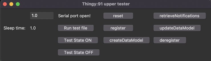
Upper Tester GUI
To get the Upper Tester to properly connect to the Thingy:91, connect the Thingy:91 to the laptop via USB and turn on the Thingy:91. Through the device manager, monitor what port the Thingy:91 connects to. In the tester.py file on line 9, change the port value to where the laptop connected to the Thingy:91 when it was powered on. Once changed, run the Upper Tester.
Flashing the Thingy:91
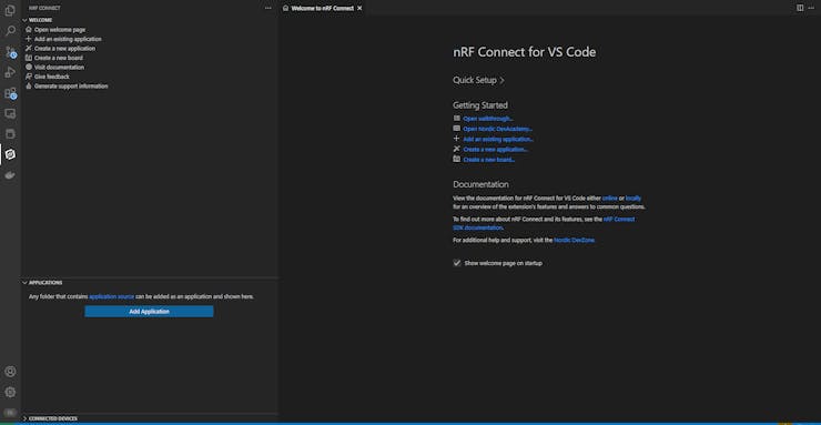
To compile this code, you will need to install the nRF Connect SDK from Nordic Semiconductor. Downloading Visual Studio Code with the SDK will allow the nRF connect app to detect Visual Studio Code and connect the two applications.
The Thingy:91 has two chips on it: the nRF9160, and the nRF52840.This means that there is an application for each chip that has to be compiled and flashed separately.
Before you flash the Thingy:91 with any code, you should follow the instructions in this link by Nordic Semiconductor to update it with the latest versions of the connectivity bridge and LTE modem firmware.
Once you have flashed your Thingy:91 with the up-to-date firmware, you can go to the next steps to compile and flash it.
Compiling the Thingy:91's nRF52840 Code
In the Visual Studio Code nRF SDK environment:
Select the add existing application option and open the traffic_light_nRF52840 folderIn the rightmost panel, under application, the traffic_light_nRF52840 will openSelect add new build configurationIn the build configurations, change the chip to thingy91_nrf52840Build ConfigurationOnce Build Configuration is completed, go to ACTIONS and select build
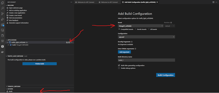
Visual Studio code highlighting build configuration, board selection, and build action for 52840
The nRF Connect SDK will create a hex file titled app_signed.hex that can be flashed onto the Thingy:91. This can be found at build/Zepher/app_signed.hex located in the traffic_light_nRF52840. This hex file can then be flashed to the Thingy:91 through the nRF Connect Programmer app
Compiling the Thingy:91's nRF9160 Code
In the Visual Studio Code nRF SDK environment:
Select "Add Existing Application" and open the traffic_light_nRF9160 folderIn the rightmost panel, under application, the traffic_light_nRF9160 will openSelect "Add New Build Configuration"In the build configurations, change the chip to `thingy_nrf9160_ns`Press the blue "Build Configuration" buttonBefore building, make sure that each Thingy:91 has a unique Device letter. This letter will correspond to which ESP32 it connects to and what name its resources have. In the nRF9160 code under include the file deployment_settings.h house the variable DEVICE_LETTER, where this can be changed.Once Build Configuration is completed, go to ACTIONS and select build
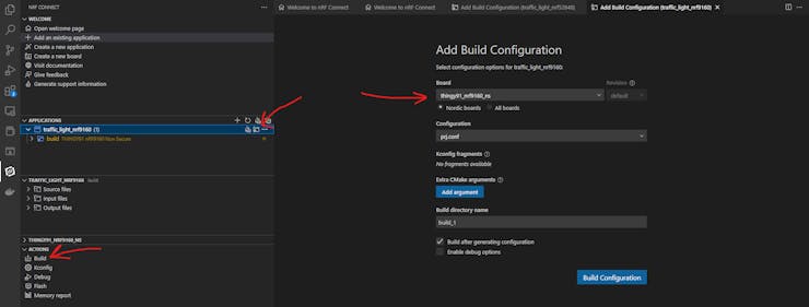
Visual Studio code highlighting build configuration, board selection, and build action for 9160
The nRF Connect SDK will create a hex file titled app_signed.hex that can be flashed onto the Thingy:91. This can be found at build/Zepher/app_signed.hex located in the traffic_light_nRF9160. This hex file can then be flashed to the Thingy:91 through the nRF Connect Programmer app
Deploying ACME CSE
We chose to use ACME as our oneM2M CSE due to its ease of visualization and control of CSE resources.
To set up ACME to run on a publicly reachable AWS EC2 instance, you will first need to create the EC2 instances and, most importantly, in that process, create a security group that specifically allows traffic to the specific port (8080) that ACME would be listening on.
Once you have the EC2 instance up and security groups configured, you can deploy ACME onto the instance by first connecting to your EC2 instance using your preferred method (EC2 instance connect or SSH are simplest), then installing git onto the EC2 instance via the command "sudo yum install git", and finally cloning ACME from its git repository, this can be done with the command: "git clone https://github.com/ankraft/ACME-oneM2M-CSE.git".
Once you have cloned the ACME CSE, you will need to checkout the development branch using the following command:
git checkout development
Amazon EC2 instances come preinstalled with Python 3.7, but ACME requires Python 3.8. Install Python 3.8 with the following command:
sudo amazon-linux-extras install python3.8
Then lastly, install of ACME’s dependencies via this command:
/usr/bin/python3.8 -m pip install -r requirements.txt
Configuring ACME CSE
After ACME and all of its dependencies have been successfully installed onto your EC2 instance, you will now need to copy this.fcp file into the init/ directory of ACME. This contains the unique definition for the FlexContainers that are used to monitor the status of the lights.
Next, launch the CSE by calling the embedded python launch script:
python3.8 -m acme --http-port 8080
Then select the default option for all of the startup options, other than when it asks for "Network Interface to bind to", where you should enter 0.0.0.0, in order to allow public traffic from the web (unless you have a network interface you would rather have it bind to), and then next when it asks for the "CSE Host address", you should enter the public IPv4 address of your AWS EC2 instance. After all startup options have been chosen, when prompted, write the configuration to the file acme.ini. Now the CSE should be running and functional, and you should see the confirmation message "CSE started".
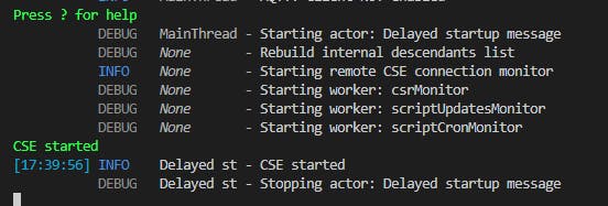
CSE Successful Startup Message
Once ACME is configured for the first time, you will need to edit the generated acme.ini [http://acme.ini/] configuration file to contain the following lines:
[server.http.cors]
; Enable CORS support for the HTTP binding.
; Default: false
enable=true
This configuration change enabled Cross Origin Requests, which is required for the web-app.
Configuring the Dashboard Web App
To allow the Dashboard Web App to create notifications for the creation of intersection application entities (AE's), the root ACP of the CSE has to be modified. Using ACME's REST Web UI, add this Access Control Record to the createACPs policy (add it as an element in the pv.acr array). This modification allows AE's with the originators of Cdashboard, and Cdashboard1 through Cdashboard4 to create Subscription resources in the CSE root.
By adding all of these originators, multiple web dashboards can be opened simultaneously. If you need more than the available 5 originators, you can always add more to the acor array.
Setting up the ESP32
This module acts as a Bluetooth Low Energy peripheral and simply reads in commands from it's BLE connection and translates those commands into GPIO instructions to our light module.
For the ESP32 and Thingy:91 to connect via Bluetooth, they need to have matching device letters. This variable that houses the device letter is in the bleControl.ino file inside the ESP32 code folder. On line 13, change the device letter to match the desired Thingy:91. Once changed, save, and you are ready to compile and flash the ESP32.
Arduino IDE is needed to compile and transfer over to ESP32.
Arduino IDE Setup
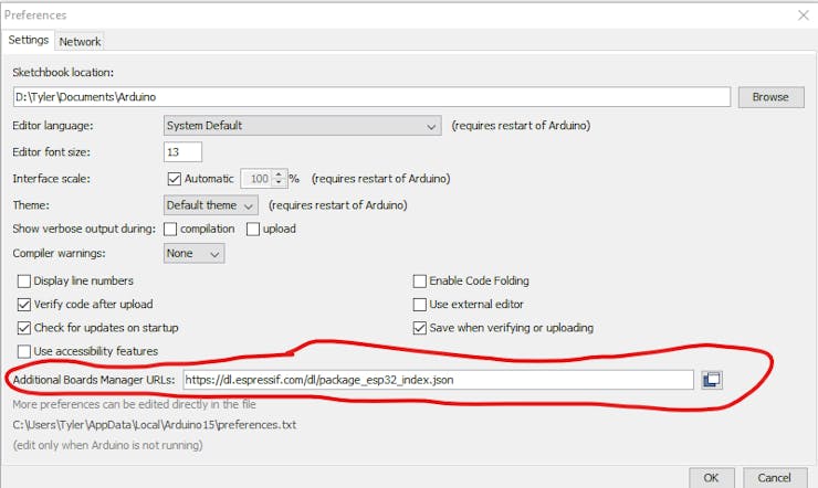
To program the ESP32, you will need to download the board packages for the ESP32.To do this, open up your Arduino IDE and go to "File -> Preferences".In the settings tab, you will see a field named "Additional Boards Manager URLs", add this URL to the field:https://dl.espressif.com/dl/package_esp32_index.json.If you already have other URLs in that box, separate them by adding a comma between them.Once you have added this URL, press "OK" in the dialog box to apply the changes.
Next, you download the board packages. Go to "Tools -> Board -> Boards Manager". Type in "esp32" in the search bar. Press Install on the result that comes up.
Programming
To program your device with this software, select the "Node32s" board and type in "Tools -> Board -> ESP32 Arduino -> Node32s".Select the correct COM/TTY port in "Tools -> Port".
While uploading the program, you will have to press and hold the "Boot Button" on the ESP32.This button is located to the right of the micro USB connector, as circled in red in the image below.
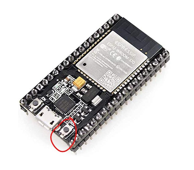
ESP32
Pinouts
Red 1 - GPIO23Yellow 1 - GPIO22Green 1 - GPIO21GND 1 - N/ARed 2 - GPIO19Yellow 2 - GPIO18Green 2 - GPIO5GND 2 - N/A
These pin assignments can be changed by modifying the r1Pin, y1Pin, g1Pin, r2pin, y2pin, and g2pin variables located at the top of the btControl.ino file.
Dashboard Web App
Web-based applications are the best platform for delivering IoT solutions to customers. By allowing users to tap into your IoT solution through just their web browser, you enable them to securely control their devices from anywhere, anytime, on any device.
Web-applications avoid the many problems of managing installations on client machines, rolling out updates to their installations, and locking down your software from piracy. It also allows you to provide your web-applications to customers in the form of Software as a Service (SaaS).
However, web-applications are not without their challenges, and it's best to closely examine your choice of software libraries and architecture before and during development.
Our web app is a React JS Single Page Application (SPA) that communicates with the ACME CSE through Ajax/XHR requests powered through Axios. The SPA architecture may be considered an anti-pattern to some developers, but it makes the most sense when working with oneM2M.
![]()
Axios provides a great API for making these HTTP requests to the CSE with JavaScript Promises, and React JS gives us a clean way of expressing UI updates using reactive programming.
React JS handles UI updates, and Axios handles HTTP requests, but between those two libraries lies our own custom rolled oneM2M EcmaScript 6 library. This ES6 library contains classes for ACP's, AE's, Subscriptions, Flex Containers, and Polling Channels. Each class has its own create, update, and retrieve methods implemented.
One very powerful feature of this library are the functions provided by the PollingChannel class. This class provides methods for starting and stopping a long-polling loop with callbacks for when notifications are received. You no longer have to write custom logic for long polling! Just supply a notification callback to start_poll() and your web-app will now receive notifications from the CSE.
When the CSE produces a notification for the Dashboard AE, it responds to the polling channel request with the notification. Next, the polling channel parses out this notification and simultaneously sends a POST request to acknowledge the received notification, and calls the user-supplied notification callback function. In our case, the notification callback is a method in our Dashboard class. This method performs the necessary UI updates using the event notification type, and the resource ID.
Contributions to ACME CSE
During development, a few changes were made to the ACME CSE to make it easier to use, and improve compliance with oneM2M.
The first change made was a "Settings" button that allows users to easily switch between viewing the long names and short names of oneM2M resources. This helped with learning the abbreviations.
Next, we discovered a bug in the ACME CSE that would cause an internal server error when creating a FlexContainer with a malformed request. While investigating this bug, we also realized that the ACME Web UI had a missing switch statement case that resulted in the UI not being updated properly, so we made changes that were merged to fix this UI bug.
Finally, we also noticed that the HTTP status code that is returned when a polling channel request expires without any notifications was incorrect. oneM2M TS-0009, table 6.32-1 maps the REQUEST_TIMEOUT response to HTTP status code 504 GATEWAY timeout. This was fixed once we pointed it out.
Web Apps and oneM2M
As stated before, we truly believe that web-applications are the best platform for delivering IoT solutions.
This may have been the first project that delivers an Application Entity that runs purely in your browser. There is no backend to the web-app. Your web-browser acts as the Application Entity and makes HTTP requests directly to the CSE. Other projects in the past have used a program running on a server that managed the oneM2M connection, and simply propagated UI updates to the browser through web-sockets. In our project, everything is in the web-browser.
In fact, you can downloadtheweb-app as a file onto your device, turn off the website EC2 instance hosting the web-app (not the ACME CSE, just the web-app), and still be able to use the web-app from the locally downloaded file. That's a very powerful capability.
In order to enable this capability, we had to address the restrictions imposed by Cross Origin Request Security (CORS). Cross Origin Request Security is a safety feature built into all modern web browsers that prevents JavaScript code from performing HTTP requests to arbitrary servers. On a web page, JavaScript code is allowed to perform HTTP requests to same host as the original website, but if it makes a request to a different host name, it is now a "cross origin request".
By default, a cross origin request is blocked by the web browser unless the requested server replies with a special CORS header that signifies the request is permitted. This mechanism prevents hackers from writing malicious JavaScript code on a website that accesses the devices in your local network through HTTP requests.
However, sometimes cross origin requests are desired. This is especially common for API endpoints where authentication and authorization are already in place by the server, and the server is meant to be public facing. This is technically also the case for our oneM2M CSE. The problem that we faced with deploying our web application is that the hostname for the web-app and the hostname for the ACME CSE were different. This means all HTTP requests from the web-app were cross origin requests. To get around this, we patched our ACME installation to allow for cross origin requests. This patch is the reason why these instructions require you to checkout the "development" branch and enable CORS in the settings.
A better solution to this issue is to use a front-end HTTP proxy such as NGINX that intercepts HTTP requests and forwards them to either the ACME CSE or the web-app. This way, both the CSE and the web-app can be served from the same hostname and port.
Code

GIthub Repository
The article was first published in hackster, November 2, 2022
cr: https://www.hackster.io/490554/cellular-based-iot-using-onem2m-testing-for-conformance-bf8df7
author: Praney Goyal, Joseph O'Brien, Tyler Sengia, Hayden Weber, Noah Schiro, Bob Flynn, SeungMyeong Jeong, Andreas Kraft, Miguel Angel Reina Ortega, Wonbae Son


