
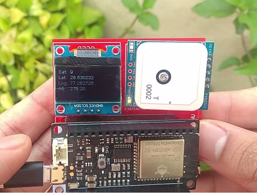
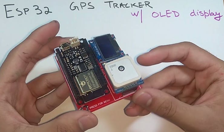
This is a GPS tracker which displays all the positional data on the OLED display. A button helps the user to interact with a UI on the OLED.
Things used in this project
Hardware components
Story
Intro
This is a GPS tracker which displays all the positional data on the OLED display. A button helps the user to interact with a UI on the OLED.
Hey, what's up, guys? Akarsh here from CETech.
The code offers a menu driven program using the onboard button, which when pressed for a short interval, cycles through menus of the GPS data like Latitude, Longitude, Altitude, Speed etc.
You can upload this data using the esp32 on the internet using wifi or Bluetooth to a smartphone.
So, in short, this project has an ESP32 which can give WiFi/Bluetooth functionality, OLED display and GPS module. Possibilities with the code are endless. I have also added a prototyping area where you can add sensors or other components to the ESP32 which is also accessible.
Parts
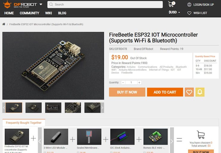
Firstly as the main part, I used an ESP32 module from DFRobot. Attached it on the PCB using some male and female headers. I used an OLED display.
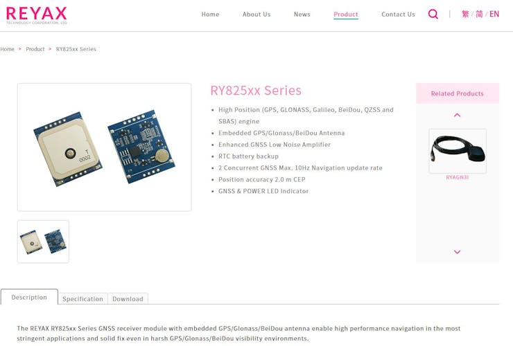
For the GPS purpose, I used a Reyax GPS module. I highly suggest this module as it is very easy to use over UART bus.
You can find the parts below:
1) ESP32 FireBeetle Module: https://www.dfrobot.com/product-1590.html
2) Reyax RYLR896 LoRa module: https://www.ebay.com/itm/REYAX-RY8253F-10Hz-GPS-Gl...
3) My PCB design: I have included the Gerber file below.
For the last two parts if you have difficulty in finding them out you can message/email me and either I can help you find it in your area or I can ship them to you if you wish.
I would also recommend to get your PCB manufactured. You can order your PCBs from PCBWAY as they offer 10 PCBs for just $5. Check out their online Gerber viewer function. With reward points you can get free stuff from their gift shop.
Theory: Understanding the GPS Module & NMEA
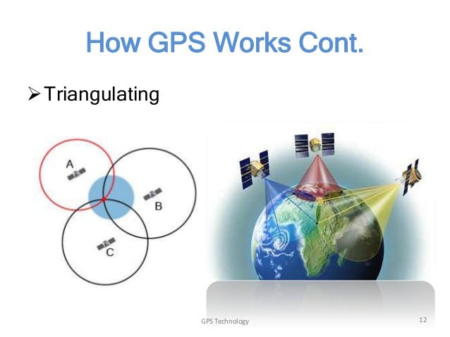
Position tracking is done through GPS using satellite communication. There are GPS satellites covering the entire earth at all times. GPS signals are weak and hence there is difficulty in finding GPS signal indoors. At a time to calculate and get an appropriate GPS location, there should be signals from at least 3 satellites at a time. More the satellites connected to your device better the accuracy of the location data.
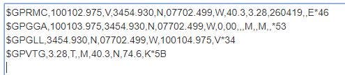
Now in the GPS module case, the module is a UART based module and sends the GPS data through the serial lines. This happens in a sequential and a proper coded manner. This coded manner is called NMEA. An example of GPS data in NMEA format is given above in the image.
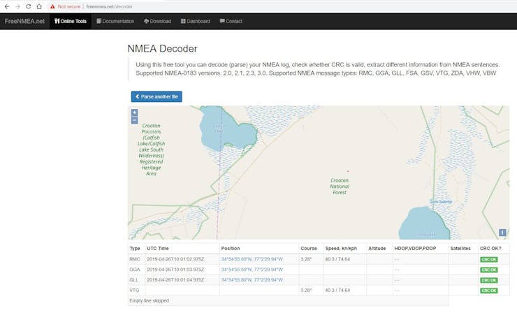
There are NMEA online decoder tools which decode the information and show it in a good graphical way. You can find one tool HERE.
Connections of the Modules in the PCB
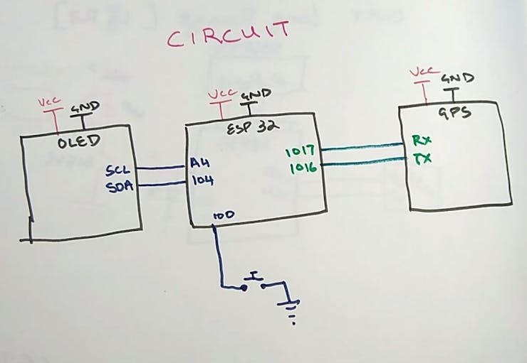
1. Both the modules will be connected the same way as in the image above.
2. When both the modules are connected, you may program the ESP32 Firebeetle board and then test the project.
All the connections shown above are done in the PCB and so there is no need for any other wiring.
Soldering & Assembly of the PCB
Solder all the parts to the PCB.
I would suggest to solder the low height components on the PCB first and then move to components with more height like the headers etc. In this case the button first then the headers.
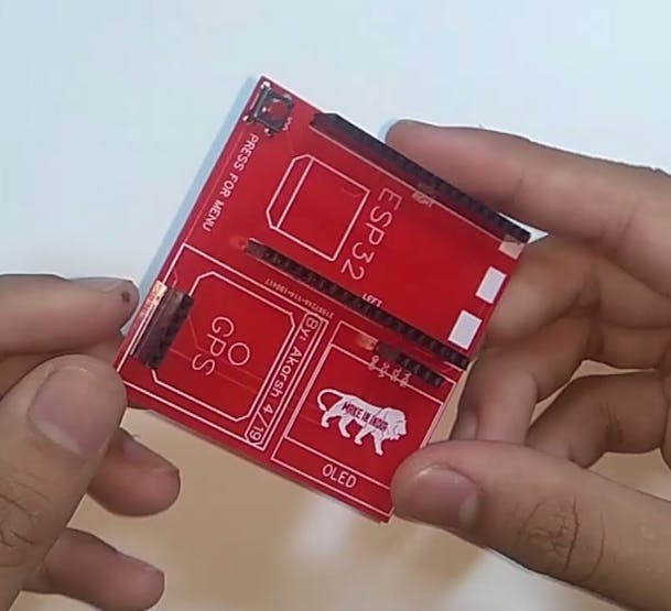
Once the headers are soldered then attach all the modules to these headers aligning according to the markings on the PCB.
Before powering the module test all the connections using a multimeter for bad solder joints and short circuits.
To program the module you can connect the esp32 module directly to your PC using a USB cable.
Coding the Project
1. Download the GitHub repository: https://github.com/akarsh98/ESP32-GPS-tracker
2. Extract the downloaded repository.
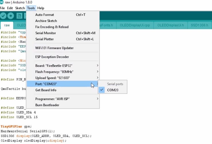
3. Open the raw sketch in the Arduino IDE.
4. Navigate to Tools > Board. Select the appropriate board that you are using, Firebeetle ESP32 in my case.
5. Select the correct comm. port by going to Tools > Port.
6. Hit the upload button.
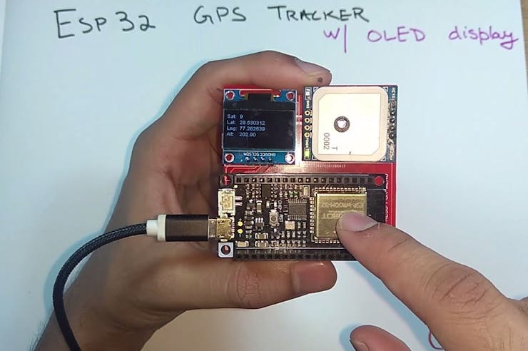
7. When the tab says Done Uploading you will see the OLED display spring up to life.
Playing with the Device
Now when you're done with the code upload you simply need to power the device using a USB cable or a battery.
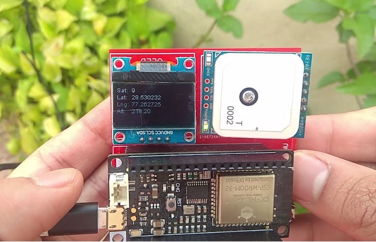
After a few seconds, GNSS LED on the GPS module will start blinking which means that the GPS signal gets latched with the satellite. Now you will also be able to the location data appearing on the OLED.
Press the GPIO0 button to interact with the device menu.
Congrats on making the project if you did, let me know in the comments below!
The article was first published in hackster, April 29, 2019
cr: https://www.hackster.io/akarsh98/esp32-gps-tracker-with-an-oled-display-0de264
author:Akarsh Agarwal


