
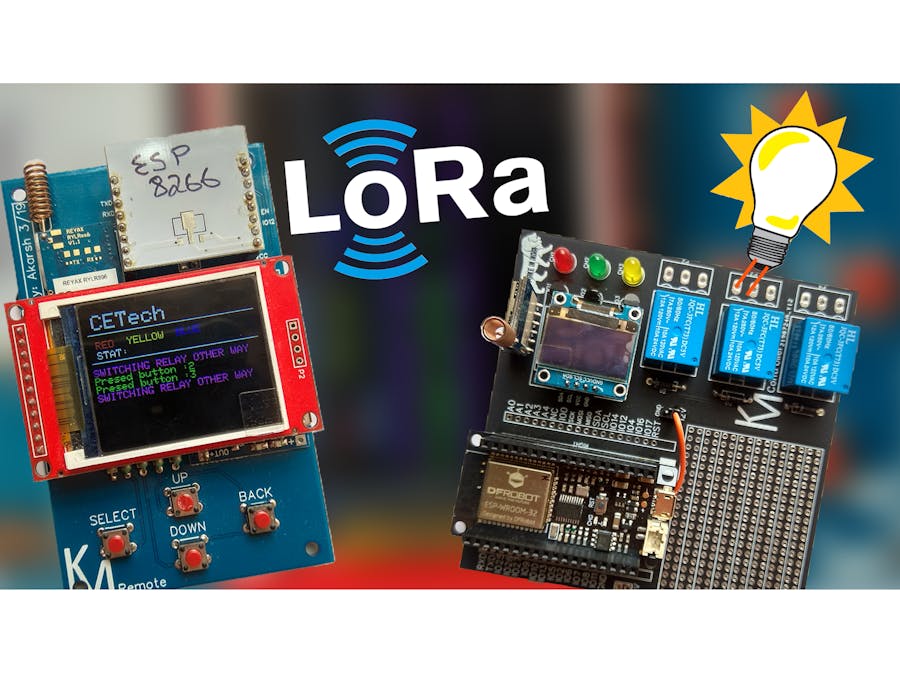
Control and automate your electrical appliances from long distances (Kms) without the presence of the internet. This is possible via LoRa.
Things used in this project
Hardware components
Story
Intro
Control and automate your electrical appliances from long distances(Kilometres) without the presence of the internet. This is possible through LoRa!
Hey, what's up, guys? Akarsh here from CETech.
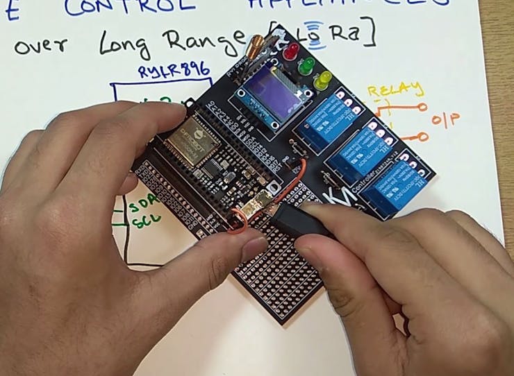
This PCB also has an OLED display and 3 relays which are connected to the ESP32. You can do anything with the code and control the relays using LoRa/WiFi/Bluetooth. So, in short, this project has an ESP32 which can give WiFi/Bluetooth functionality, LoRa module, OLED display and 3 relays. Possibilities with the code are endless. I have also added a prototyping area where you can add sensors or additional relays to the ESP32 which is also accessible.
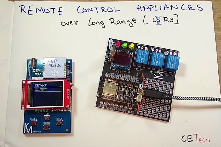
This is a type of part 2 of a project. So for any control system like this one you need a remote to control the things.
I made a LoRa based remote which you can check out here: https://www.instructables.com/id/LoRa-Remote-Cont...
In my case, I am using the remote and this controller together and they work like a charm!
Parts
Firstly as the main part, I used an ESP32 module from DFRobot. Attached it on the PCB using some male and female headers. I used an OLED display.
For the LoRa purpose, I used an RYLR896. I highly suggest this module as it is very easy to use over UART using AT commands.
You can find the parts below:
1) ESP32 FireBeetle Module: https://www.dfrobot.com/product-1590.html
3) My PCB design: I have included the Gerber file below.
For the last two parts if you have difficulty in finding them out you can message/email me and either I can help you find it in your area or I can ship them to you if you wish.
I would also recommend to get your PCB manufactured. You can order your PCBs from PCBWAY as they offer 10 PCBs for just $5. Check out their online Gerber viewer function. With reward points you can get free stuff from their gift shop.
Understanding the Reyax Module and How to Use It. (OPTIONAL : You May Skip Reading This Step If Not Interested About the Working)
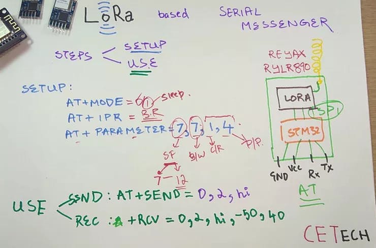
1. The LoRa module we have is a UART module which is configured using AT commands.
2. The module houses a STM32 MCU which does all the talking to the SPI LoRa module onboard the RYLR896.
3. The commands in the picture are basic ones you may refer to this document for more: REYAX-Lora-AT-COMMAND-GUIDE
4. I still strongly recommend you to go through my YouTube video where I explain this properly.
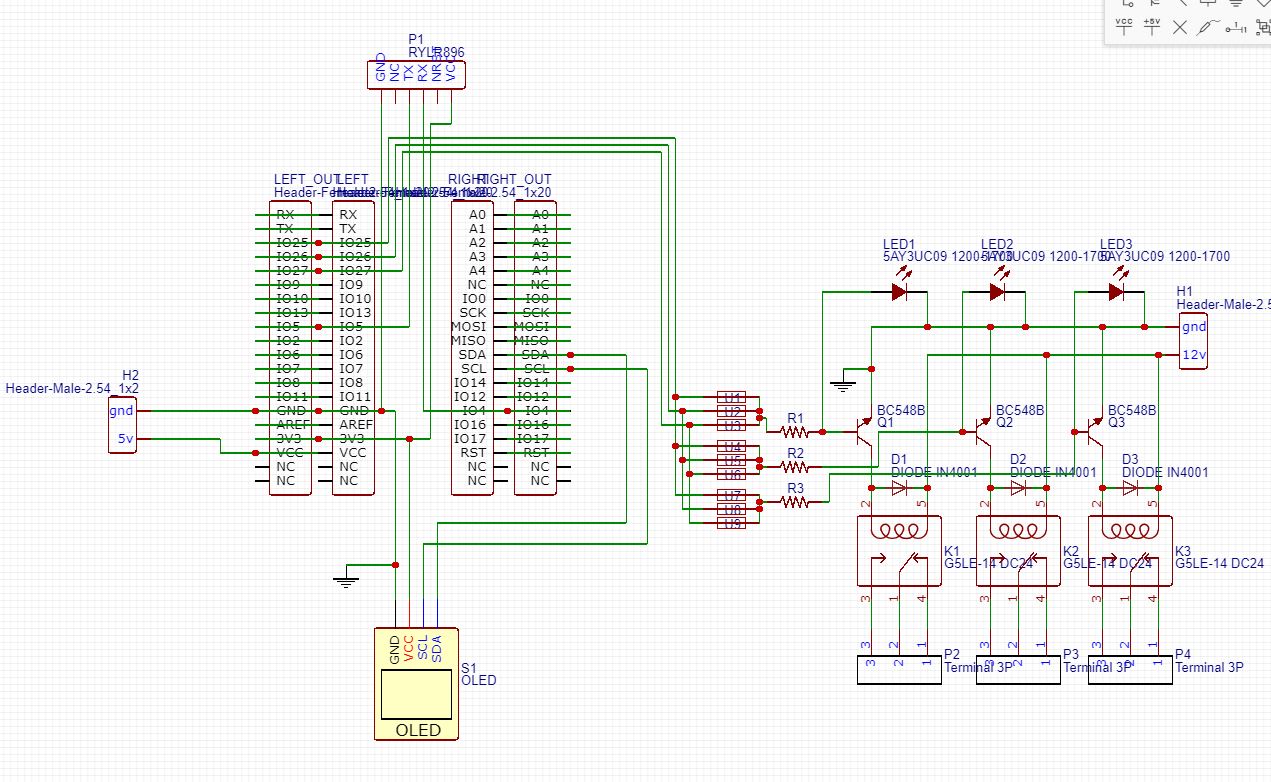
Connections of the Modules in the PCB
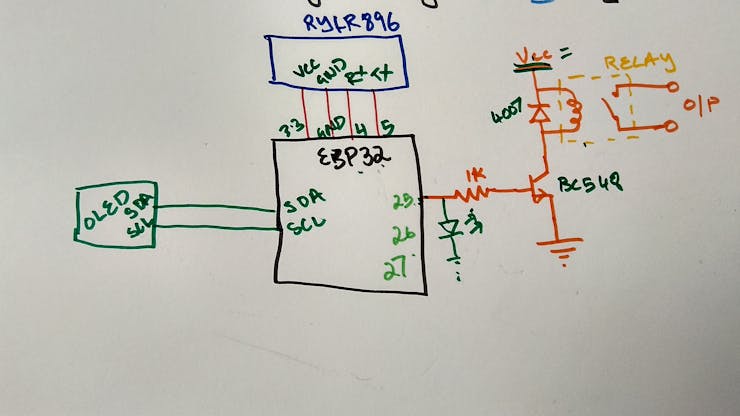
1. Both the modules will be connected the same way as in the image above.
2. When both the modules are connected, you may program the modules one by one and then test the project.
3. You will need to connect the transistor circuit multiple times for as many relays you connect.
All the connections shown above are done in the PCB and so there is no need for any other wiring.
Soldering of the PCB
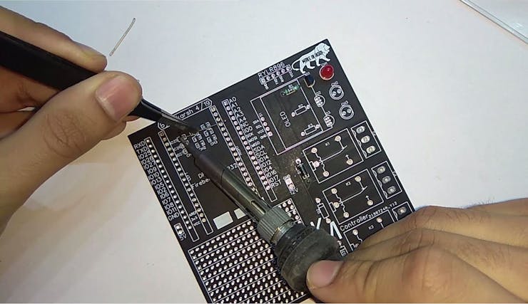
Solder all the components to the PCB.
I would suggest to solder the low height components on the PCB first and then move to components with more height like the headers etc.
Before powering the module test all the connections using a multimeter for bad solder joints and short circuits.
To program the module you can connect the esp32 module directly to your PC using a USB cable.
Download and Set Up the Arduino IDE
Download the Arduino IDE from here.
1. Install the Arduino IDE and open it.
2. Go to File > Preferences
3. Add http://arduino.esp8266.com/versions/2.5.0/package_esp8266com_index.json the Additional Boards Manager URLs.
4. Go to Tools > Board > Boards Manager
5. Search for ESP8266 and then install the board.
6. Restart the IDE.
Coding the Project
Download the GitHub repository: https://github.com/akarsh98/ESP32-LoRa-Relay-Control-Code-and-Circuit
2. Extract the downloaded repository.
3. Copy the libraries from the downloaded repository to the Library folder in Arduino sketch folder.
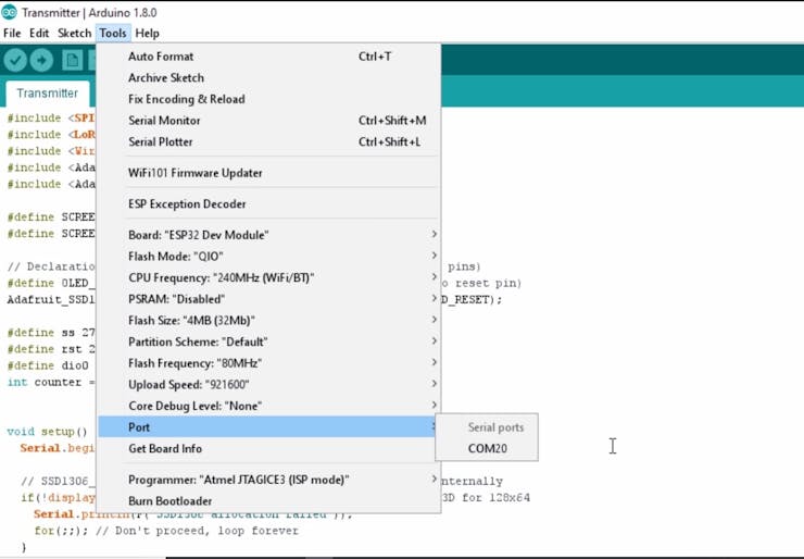
4. Open the Transmitter sketch in the Arduino IDE.
5. Navigate to Tools > Board. Select the appropriate board that you are using, Firebeetle ESP32 in my case.
6. Select the correct comm. port by going to Tools > Port.
7. Hit the upload button.
8. When the tab says Done Uploading you should repeat the above steps with the receiver module to upload the code.
Playing With the Device
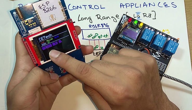
1. Just power the device on, you can hit different buttons on the remote to see the relays click.
2. To make this device work you must have a LoRa based remote, you can find the one that I built over here:
3. CONGO! the device is working as expected.
Schematics
circuit
The article was first published in hackster, April 21, 2019
cr: https://www.hackster.io/akarsh98/control-home-appliances-over-lora-lora-remote-control-603ffe
author: Akarsh Agarwal


